Multi-stage transmission shaft device and system

A technology of transmission shaft and transmission bearing, applied in the field of shaft transmission, can solve the problems of high cost, difficult realization, complex structure of multi-station winding structure, etc.

Active Publication Date: 2021-04-02
深圳市大族贝瑞装备有限公司
View PDF5 Cites 0 Cited by
  • Summary
  • Abstract
  • Description
  • Claims
  • Application Information

AI Technical Summary

Problems solved by technology

[0006] The technical problem to be solved by the present invention is to provide a multi-stage transmission shaft device and system for the above-mentioned defects of ...

Method used


Image

  • Multi-stage transmission shaft device and system
  • Multi-stage transmission shaft device and system
  • Multi-stage transmission shaft device and system

Examples


Embodiment Construction

[0028] Now in conjunction with the accompanying drawings, the preferred embodiments of the present invention will be described in detail.

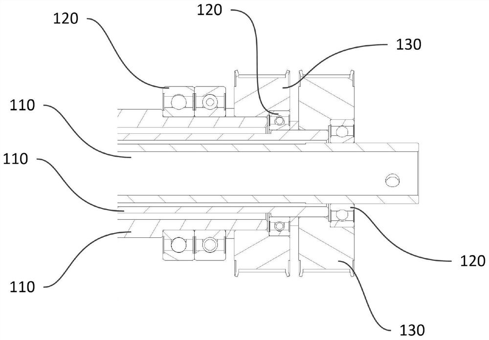
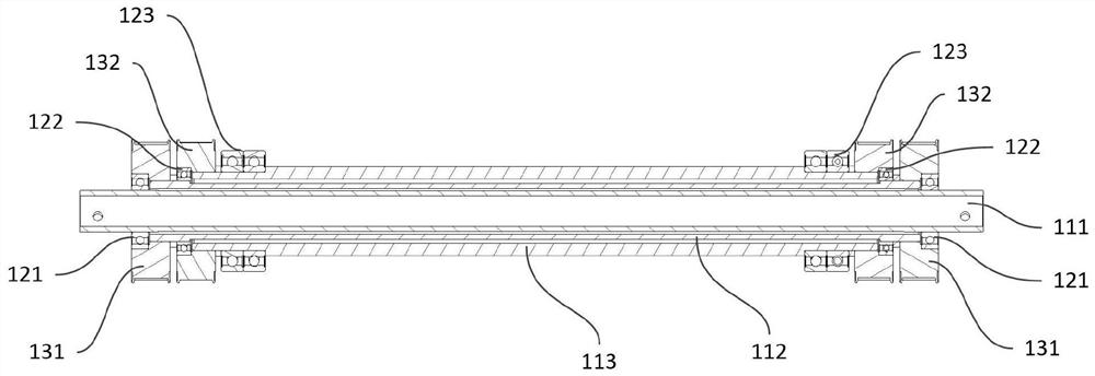
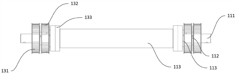
[0029] Such as Figure 1 to Figure 4 As shown, the present invention provides a preferred embodiment of a multi-stage drive shaft arrangement.

[0030] A multi-stage transmission shaft device, including a transmission shaft 110, a bearing 120 and a synchronous wheel 130, forming a multi-stage transmission structure. There are multiple transmission shafts 110, which are all coaxially stacked and sleeved. The two ends of each transmission shaft 110 Bearings 120 are provided on the sides, and the inner side of the bearing 120 is fixedly connected with the outer side of the corresponding transmission shaft 110, and the inner side of the synchronous wheel 130 is respectively connected to the outer side and adjacent side of the transmission bearing at one end of the adjacent inner transmission shaft 110. The outer side of the outer transmission...


PUM


Abstract

A multi-stage transmission shaft device and system, the multi-stage transmission shaft device comprising: a plurality of transmission shafts (110) coaxially stacked and sleeved; the bearings (120) arearranged on the side faces of the two ends of each transmission shaft (110) respectively, and the inner sides of the bearings (120) are fixedly connected with the outer sides of the corresponding transmission shafts (110); and the inner side of the synchronizing wheel (130) is fixedly connected with the outer side of the transmission bearing close to one end of the adjacent inner transmission shaft (110) and the outer side of the adjacent outer transmission shaft (110) respectively.

Description

technical field [0001] The invention relates to the technical field of shaft transmission, in particular to a multistage transmission shaft device and system. Background technique [0002] With the rapid development of the lithium battery industry, lithium battery cell winding equipment is also constantly being updated, especially the use of multi-station winding to realize cell winding. [0003] During multi-station winding, each station is assigned to complete one or more processes, and they all work independently. For example, through the turret module (including the inner ring and the outer ring that can rotate with each other), each winding station is installed on the inner ring of the turret module, and the angle changes with the rotation of the inner ring of the turret module, Realize station switching. However, if the drive module of each station is directly installed on the inner ring of the turret module, there are several problems: [0004] (1) It is necessary ...

Claims


Application Information

Patent Timeline
IPC IPC(8): F16C3/02F16H57/00F16H7/02H02K7/10H01M6/00H01M6/14H01M10/04H01M10/052H01M10/0587
CPCF16H57/0025F16H57/0018F16H7/02F16C3/02H02K7/1004H01M10/0587H01M10/0409H01M10/052H01M6/005H01M6/14Y02E60/10Y02P70/50
Inventor 汤辉汤志为杨凯郑付成黄东海丰凯金攀熊佳远高云峰
Owner 深圳市大族贝瑞装备有限公司
Why Eureka
Try Eureka