
Capacitive proximity switch convenient to install

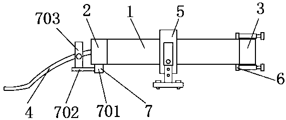
A proximity switch, easy-to-install technology, used in electronic switches, electrical components, pulse technology, etc., can solve problems such as damage, disordered wiring, easy to fall off, etc., to prevent disordered wiring, facilitate adjustment, and improve stability. Effect

Inactive Publication Date: 2020-02-28
西安德创自动化工程有限公司
View PDF3 Cites 0 Cited by
  • Summary
  • Abstract
  • Description
  • Claims
  • Application Information

AI Technical Summary

Problems solved by technology

However, the proximity switch is clamped by the elastic clip groove, which is not stable enough and is prone to fall off. At the same time, the installation height of the proximity switch cannot be adjusted. It will be in contact with the collision object, and there will still be some damage. The connecting wire of the proximity switch is not bound by a tightening device when placed, and it is easy to cause wiring confusion

Method used


Image

  • Capacitive proximity switch convenient to install
  • Capacitive proximity switch convenient to install
  • Capacitive proximity switch convenient to install

Examples


Embodiment 1

[0023] Such as figure 1 As shown, a capacitive proximity switch that is easy to install includes a switch housing 1, one end of the switch housing 1 is fixedly installed with a terminal 2, and the other end of the switch housing 1 is fixedly installed with an induction head 3, and the terminal 2 is connected with a connection line 4, the outer surface of the switch housing 1 is connected with a portable fixing device 5 near the middle position, the outer surface of the induction head 3 is connected with a buffer protection device 6, and the outer surface of the wiring head 2 A wire harness device 7 is connected to an outer position close to the connection line 4 , and a retractable mechanism 8 is provided on the portable fixing device 5 .

Embodiment 2

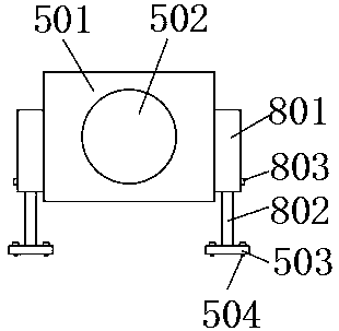
[0025] On the basis of Embodiment 1, such as figure 2 As shown, the portable fixing device 5 is composed of a fixing sleeve 501, a fixing notch 502, a telescoping mechanism 8, a mounting plate 503 and a mounting pin 504. The fixing sleeve 501 is sleeved on the outer surface of the switch housing 1, and the fixing The notch 502 is opened inside the fixed sleeve 501, the mounting plate 503 is located below the fixed sleeve 501, and a telescopic mechanism 8 is provided between the mounting plate 503 and the fixed sleeve 501, and the mounting pin 504 penetrates the mounting plate 503 The interior of the proximity switch can be stably fixed by the portable fixing device 5 .

Embodiment 3

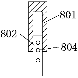
[0027] On the basis of embodiment one and embodiment two, such as image 3 As shown, the telescopic mechanism 8 is composed of a connecting rod 801, a telescopic rod 802, a limit pin 803 and a limit hole 804. The connecting rod 801 is fixedly installed on both sides of the fixed sleeve 501. The top end of the telescopic rod 802 extends to the inside of the connecting rod 801, and the bottom end of the telescopic rod 802 is fixed on the upper surface of the mounting plate 503, the end of the limit pin 803 extends to the inside of the connecting rod 801, and the limit hole 804 is uniform The telescopic rod 802 is distributed on the outer surface of the telescopic rod 802, and the telescopic rod 802 is fixedly connected with the connecting rod 801 through the limit pin 803 inserted into the limit hole 804, and the installation height of the proximity switch can be adjusted conveniently through the telescopic mechanism 8.


PUM


Abstract

The invention discloses a capacitive proximity switch convenient to install including a switch shell, a connector lug is fixedly installed at one end of the switch shell. An inductive head is fixedlymounted at the other end of the switch shell; the outer surface of the connector lug is connected with a connecting wire; a portable fixing device is connected to the position, close to the middle, ofthe outer surface of the switch shell, a buffer protection device is connected to the outer side of the inductive head, a wire bunching device is connected to the position, close to the outer side ofthe connecting wire, of the outer surface of the connector lug, and a telescopic mechanism is arranged on the portable fixing device. The invention relates to a capacitive proximity switch convenientto install. According to the capacitive proximity switch convenient to install, a proximity switch can be conveniently installed and fixed, meanwhile, the installation height of the proximity switchcan be conveniently adjusted, an induction head of the proximity switch can be buffered and protected, meanwhile, the induction head does not make direct contact when collided, and a connecting wire of the proximity switch can be tightened.

Description

technical field [0001] The invention relates to the field of proximity switches, in particular to a capacitive proximity switch which is easy to install. Background technique [0002] Proximity switch, also known as contactless proximity switch, is an ideal electronic switch sensor. When the metal detection body is close to the sensing area of ​​the switch, the switch can quickly issue electrical instructions without contact, pressure, and sparks, and accurately reflect the position and stroke of the motion mechanism. Even if it is used for general stroke control, its positioning accuracy and operation The frequency, service life, convenience of installation and adjustment, and adaptability to harsh environments are incomparable to ordinary mechanical limit switches. It is widely used in machine tools, metallurgy, chemical industry, textile and printing industries. In the automatic control system, it can be used as the link of limit, count, position control and automatic p...

Claims


Application Information

Patent Timeline
IPC IPC(8): H03K17/955
CPCH03K17/955
Inventor 李建飞
Owner 西安德创自动化工程有限公司
Learn More