

Non-woven fabric plane mask
A technology of non-woven fabrics and masks, applied in the field of masks, can solve the problems of not being able to distinguish the front and back of masks, and achieve the effects of improving intimacy, smooth breathing, and rapid perception
- Summary
- Abstract
- Description
- Claims
- Application Information
AI Technical Summary
Problems solved by technology
Method used
Image

Examples
Embodiment 1
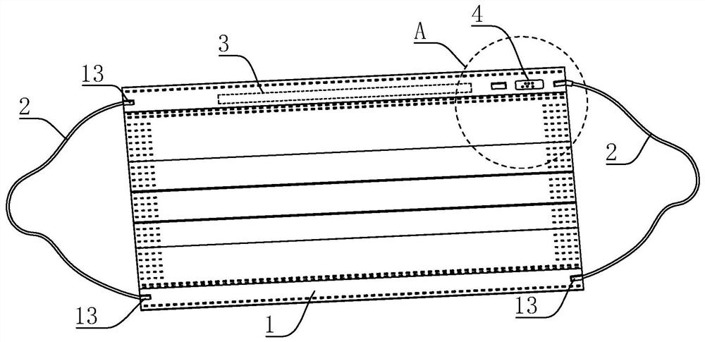
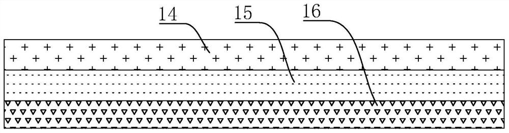
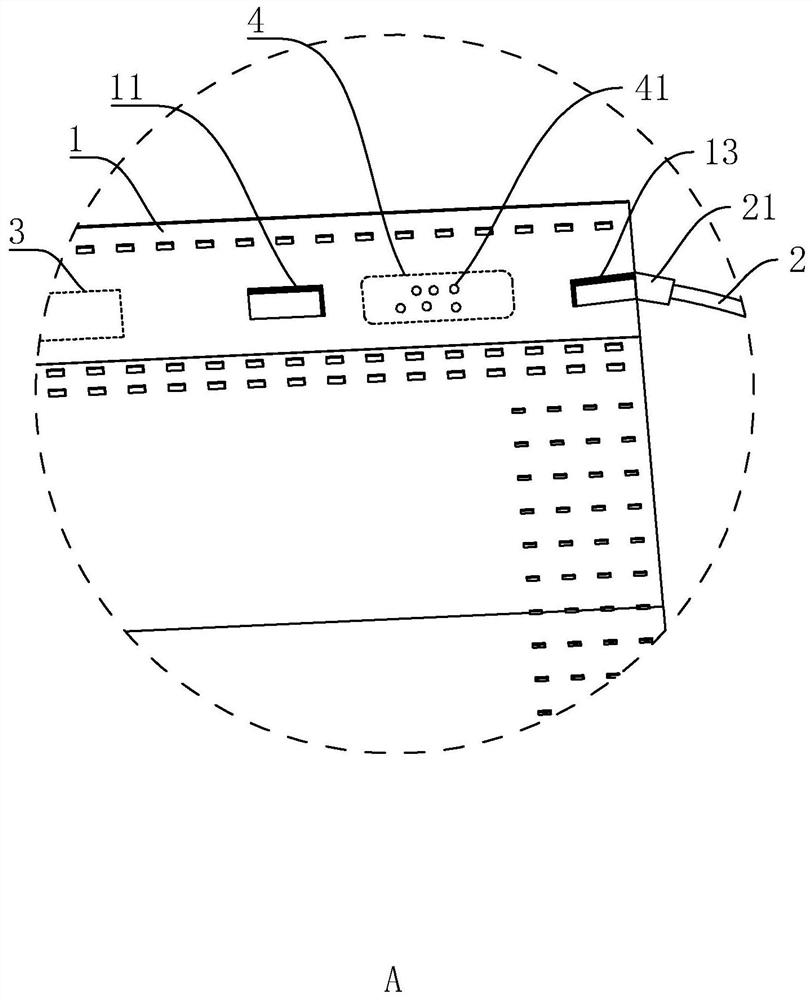
[0041] refer to figure 1 and figure 2 , the non-woven flat mask includes a mask body 1, two elastic ear straps 2, a nose bridge strip 3 and an identification part 4. The mask body 1 is in the shape of a rectangular sheet, and the mask body 1 includes water-blocking layers that are superimposed in sequence. Layer 14, filter layer 15 and water absorption layer 16, and all three are non-woven fabric materials.
[0042] refer to figure 1 and figure 2 , the nose bridge strip 3 is arranged at the top middle position of the mask body 1, and the identification part 4 is arranged at a corner of the mask body 1. When the mask body 1 is not worn, the identification part 4 and the nose bridge strip 3 are on the same horizontal line, and the recognition The part 4 is located on the right side of the nose bridge strip 3 (here the position of the identification part 4 relative to the nose bridge strip 3 is based on figure 1 Shown in the placement position of middle mask body 1, and fi...
Embodiment 2
[0050] refer to Figure 4 The difference between this embodiment and Embodiment 1 is that the identification part 4 is located on the left side of the nose bridge strip 3 (here the position of the identification part 4 relative to the nose bridge strip 3 is based on Figure 4 Shown in the placement position of middle mask body 1, and Figure 4 One side of the mask body 1 seen in the figure is the front side, that is, the side that does not touch the face when worn), and the identification part 4 and the nose bridge strip 3 form a unique positional relationship for the user to determine the front and back sides of the mask body 1 through touch ("Forming a unique positional relationship" here refers to: Figure 4 From the angle of view, the identification part 4 is located on the left side of the nose bridge strip 3).
[0051] The implementation principle of embodiment 2 is: if the identification part 4 is located on the left side of the nose bridge strip 3, then the mask body...
Embodiment 3
[0053] refer to Figure 5 The difference between this embodiment and Embodiment 1 and Embodiment 2 is that the identification part 4 is located in the lower right corner of the mask body 1, that is, the lower right corner of the nose bridge strip 3, (the position of the identification part 4 relative to the nose bridge strip 3 ,is based on Figure 5 Shown in the placement position of middle mask body 1, and Figure 5 One side of the mask body 1 seen in the figure is the front side, that is, the side that does not touch the face when worn), and the identification part 4 and the nose bridge strip 3 form a unique positional relationship for the user to determine the front and back sides of the mask body 1 through touch ("Forming a unique positional relationship" here refers to: Figure 5 From the angle of view, the identification part 4 is located at the lower right corner of the nose bridge strip 3), the mask body 1 is formed with a second barrier point 12 by ultrasonic spot w...
PUM
| Property | Measurement | Unit |
|---|---|---|
| Length | aaaaa | aaaaa |
Abstract
Description
Claims
Application Information