
Full-automatic chamfering equipment for bolts

A fully automatic, chamfering technology, used in metal processing equipment, clamping, supporting and other directions, can solve the problems of easy deviation of bolt chamfering, and achieve the effect of solving difficult control, scientific and reasonable structure, and safe and convenient use.

Pending Publication Date: 2021-04-06
金道亮
View PDF11 Cites 1 Cited by
  • Summary
  • Abstract
  • Description
  • Claims
  • Application Information

AI Technical Summary

Problems solved by technology

[0008] The purpose of the present invention is to provide a fully automatic bolt chamfering equipment to solve the problem that manual alignment of bolt chamfers is prone to deviation in the above-mentioned background technology

Method used


Image

  • Full-automatic chamfering equipment for bolts
  • Full-automatic chamfering equipment for bolts
  • Full-automatic chamfering equipment for bolts

Examples


Embodiment Construction

[0035] The following will clearly and completely describe the technical solutions in the embodiments of the present invention with reference to the accompanying drawings in the embodiments of the present invention. Obviously, the described embodiments are only some of the embodiments of the present invention, not all of them. Based on the embodiments of the present invention, all other embodiments obtained by persons of ordinary skill in the art without making creative efforts belong to the protection scope of the present invention.

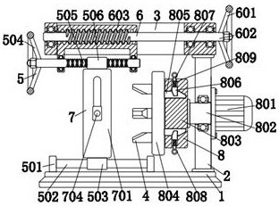
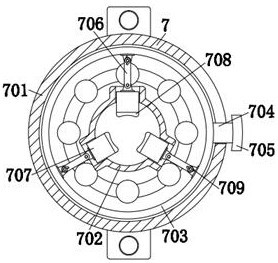
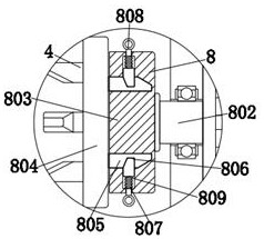
[0036] see Figure 1-6 , the present invention provides a technical solution: a fully automatic chamfering equipment for bolts, including a base 1, a vertical plate 2, a slot plate 3 and a cutter head 4, the upper right side of the base 1 is fixedly connected with the vertical plate 2, and the vertical plate The upper end of the plate 2 is fixedly connected with the slot plate 3, the base 1 fixes the slot plate 3 through the vertical plate 2, and...


PUM


Abstract

The invention discloses full-automatic chamfering equipment for bolts. The full-automatic chamfering equipment for bolts comprises a base, a vertical plate, a groove plate and a tool bit, wherein the tool bit is arranged on the left side of the vertical plate; a reciprocating device is installed on the left side of the upper end of the base; the reciprocating device comprises supports, a transverse rod, a sliding sleeve, a first handle, a lead screw and a threaded pipe; and the left end of the lead screw is fixedly connected with the first handle. The full-automatic chamfering equipment for bolts is scientific and reasonable in structure and safe and convenient to use; and through cooperation of a circular ring clamping groove, a curved plate, a circular ring, connecting rods, sliding blocks, rubber pads and volute spiral springs, the curved plate is pressed by hands to be pushed upwards, the curved plate pushes the multiple sliding blocks to move outwards at the same time through the circular ring and the connecting rods to compress the volute spiral springs, then bolts are fed into the inner wall of the circular ring clamping groove, then the curved plate is loosened, the volute spiral springs enable the sliding blocks to move towards the inner side through the connecting rods so that the rubber pads can abut against a screw rod, center positioning of the screw rod is completed, and the problem that deviation is likely to occur when bolts are manually aligned for chamfering is solved.

Description

technical field [0001] The invention relates to the technical field of bolt chamfering, in particular to a fully automatic bolt chamfering equipment. Background technique [0002] The role of bolt chamfering is to avoid damage to parts, otherwise sharp edges may easily damage or cut fingers, and second, it can play a good guiding role. [0003] Although the chamfering equipment of the prior art can complete the chamfering of bolts, the following problems still exist: [0004] 1. Manually aligning the chamfer of the bolt is prone to deviation; [0005] 2. The problem of poor control of the size of the bolt chamfer; [0006] 3. The problem that the size of the bolt chamfer cannot be adjusted; [0007] 4. The problem of cumbersome steps in replacing the cutter head. Contents of the invention [0008] The purpose of the present invention is to provide a fully automatic bolt chamfering equipment to solve the problem that manual alignment of bolt chamfers is prone to deviati...

Claims


Application Information

Patent Timeline
Patent Type & Authority Applications(China)
IPC IPC(8): B23D79/00B23Q3/00B23Q5/28
CPCB23D79/00B23Q3/00B23Q5/28
Inventor 不公告发明人
Owner 金道亮
Learn More