
Injection mold with high-efficiency cooling performance and high stability

An injection mold, stability technology, applied in the direction of non-rotational vibration suppression, etc., can solve the problems of positive injection mold production cost, reduce mold service life, poor cooling effect, etc., achieve high-efficiency cooling, reduce vibration, and not easy damaged effect

Inactive Publication Date: 2021-04-06
李元春
View PDF0 Cites 1 Cited by
  • Summary
  • Abstract
  • Description
  • Claims
  • Application Information

AI Technical Summary

Problems solved by technology

[0003] Although the existing injection mold has a cooling function, its cooling effect is not good, and the cooling effect is mostly controlled by electric equipment, etc. In this way, the cooling function is increased, and the production cost of the injection mold is correspondingly increased; secondly, During injection molding, when the movable mold and the fixed mold are attached, vibration will be generated, which will reduce the service life of the mold. Therefore, we have designed an injection mold with high-efficiency cooling and high stability to solve the above problems

Method used


Image

  • Injection mold with high-efficiency cooling performance and high stability
  • Injection mold with high-efficiency cooling performance and high stability
  • Injection mold with high-efficiency cooling performance and high stability

Examples


Embodiment Construction

[0024] The following will clearly and completely describe the technical solutions in the embodiments of the present invention with reference to the accompanying drawings in the embodiments of the present invention. Obviously, the described embodiments are only some, not all, embodiments of the present invention.

[0025] In describing the present invention, it should be understood that the terms "upper", "lower", "front", "rear", "left", "right", "top", "bottom", "inner", " The orientation or positional relationship indicated by "outside", "front end", "rear end", "both ends", "one end" and "the other end" are based on the orientation or positional relationship shown in the drawings, and are only for the convenience of describing this The invention and the simplified description do not indicate or imply that the device or element referred to must have a specific orientation, be constructed and operate in a specific orientation, and thus should not be construed as limiting the p...


PUM


Abstract

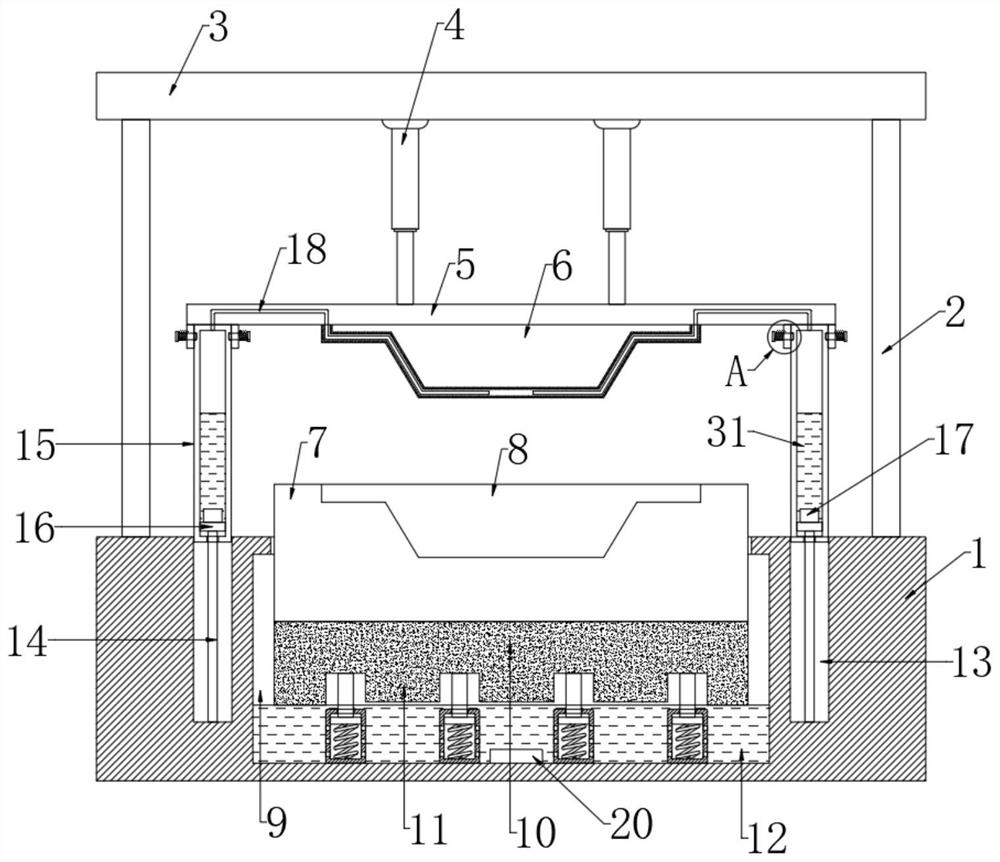
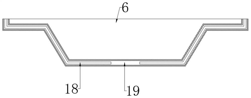
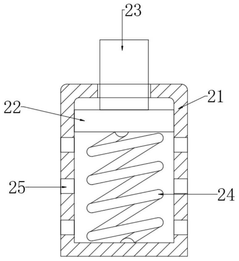
The invention discloses an injection mold with high-efficiency cooling performance and high stability. The injection mold comprises a base; four supporting columns are fixedly connected to the base; the upper ends of the four supporting columns are jointly and fixedly connected with a top plate; the bottom of the top plate is fixedly connected with two hydraulic cylinders; the output ends of the two hydraulic cylinders are jointly and fixedly connected with a mounting plate; a movable mold is mounted at the bottom of the mounting plate; a first cooling cavity is formed in the base; a fixed mold is arranged in the first cooling cavity and penetrates through the upper end of the base; a mold groove is formed in the upper end of the fixed mold; and a heat insulation plate is fixedly connected to the bottom of the fixed mold. According to the injection mold with high-efficiency cooling performance and high stability, the structure is reasonable, not only can the movable mold and the fixed mold be stably attached, but also the fixed mold can be buffered and damped, and thus the movable mold and the fixed mold can be protected against damage; and meanwhile, the movable mold and the fixed mold can be cooled at the same time, the cooling effect is good, and other driving equipment is not needed, so that the injection mold is more practical and energy-saving, and the manufacturing cost is lower.

Description

technical field [0001] The invention relates to the technical field of injection molds, in particular to an injection mold with efficient cooling and high stability. Background technique [0002] Injection mold is a tool for producing plastic products; it is also a tool for giving plastic products complete structure and precise dimensions. Injection molding is a processing method used in the mass production of certain complex-shaped parts. Specifically, it refers to injecting the heated and melted plastic into the mold cavity under high pressure from the injection molding machine, and after cooling and solidifying, a molded product is obtained. Injection molds are divided into thermosetting plastic molds and thermoplastic plastic molds according to the molding characteristics. Among them, the hot pressing mold can be divided into three types: overflow type, semi-overflow type and non-overflow type according to the overflow method, and the injection mold can be divided into...

Claims


Application Information

Patent Timeline
Patent Type & Authority Applications(China)
IPC IPC(8): B29C45/33B29C45/73F16F15/04
CPCB29C45/33B29C45/7312F16F15/04
Inventor 李元春
Owner 李元春
Learn More