Fabricated reinforced concrete beam-column joint
A technology of reinforced concrete columns and reinforced concrete beams, which is applied in the field of prefabricated reinforced concrete beam-column joints, can solve problems such as low installation efficiency and difficult quality inspection, and achieve the goals of improving structural bearing capacity, strong operability, and reducing detection difficulty Effect
- Summary
- Abstract
- Description
- Claims
- Application Information
AI Technical Summary
Problems solved by technology
Method used
Image

Examples
specific Embodiment approach 1
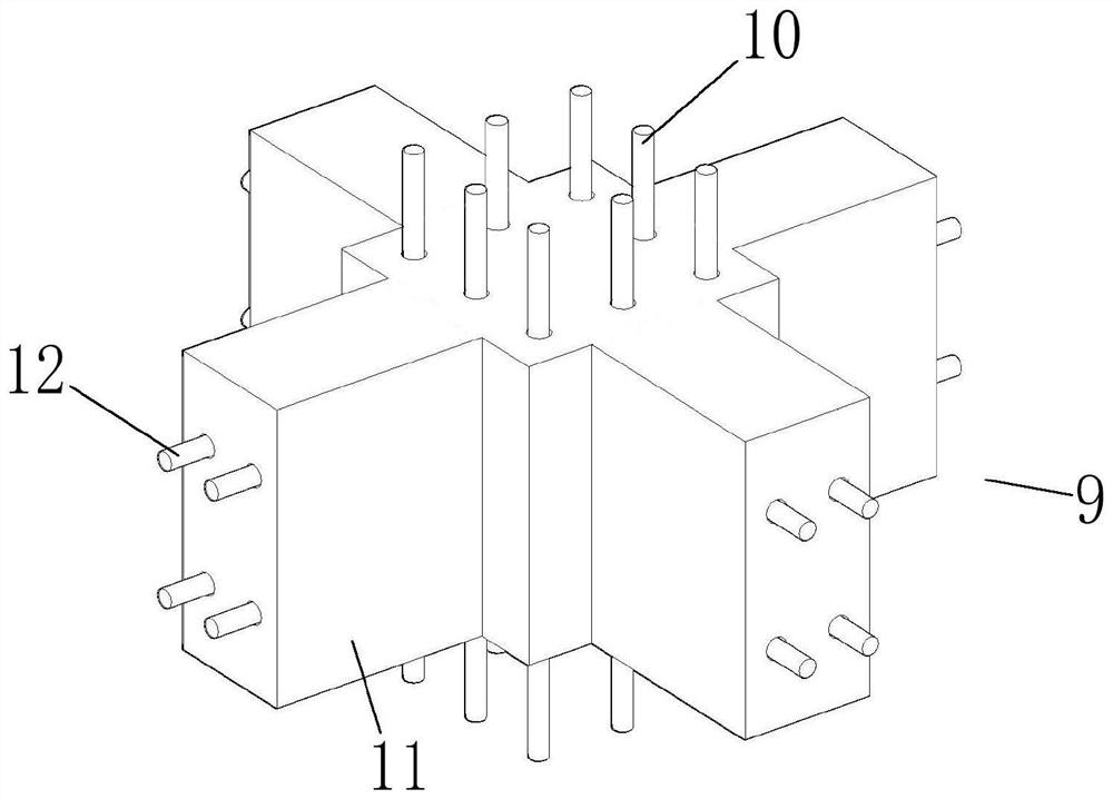
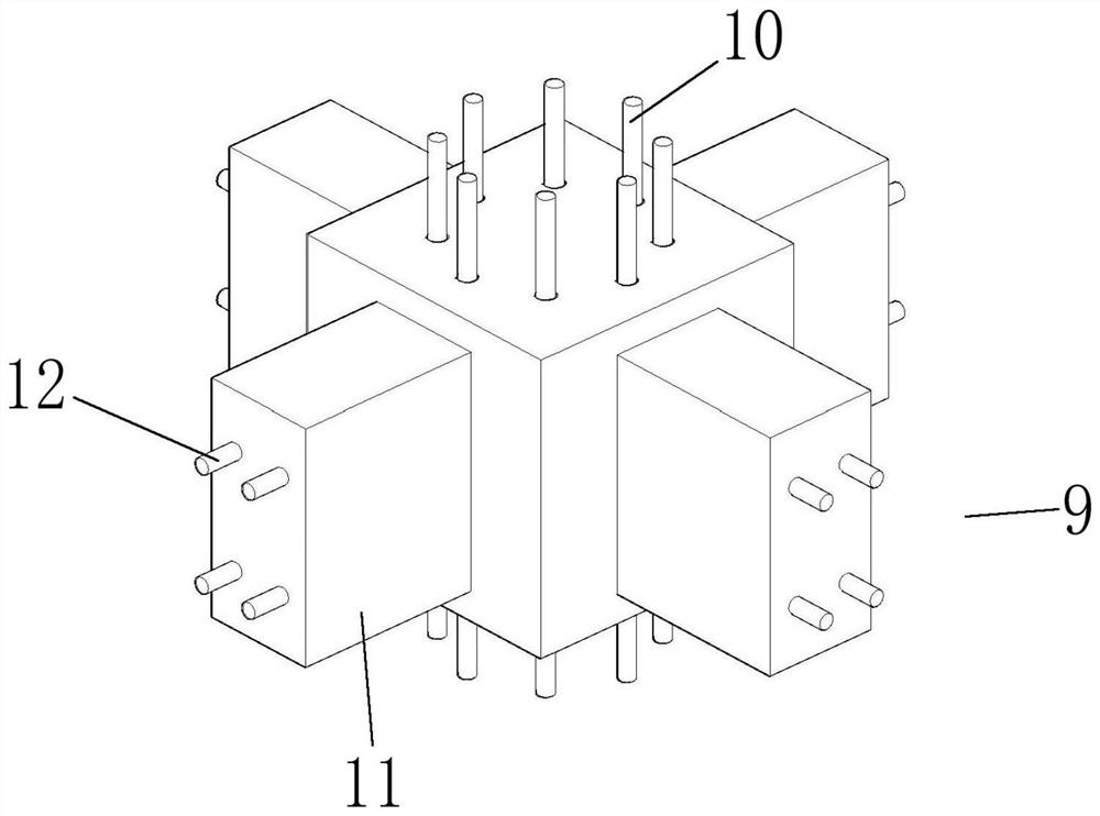
[0042]A prefabricated reinforced concrete beam-column node 9, including vertical longitudinal reinforcement 10, transverse longitudinal reinforcement 12 and at least two adjacent beam unit connection ends 11, the vertical longitudinal reinforcement 10 can pass through the installation hole of the vertical connection device 1 5 and connected with the vertical node connection plate 2, so that the top or bottom surface of the fabricated reinforced concrete node 9 coincides with the vertical node connection plate 2; the transverse longitudinal reinforcement 12 can pass through the installation hole 22 of the transverse connection device 18 and connect with the transverse node The connecting plate 19 is connected so that the beam element connecting end 11 and the transverse node connecting plate 19 coincide (such as figure 1 , 2 ).
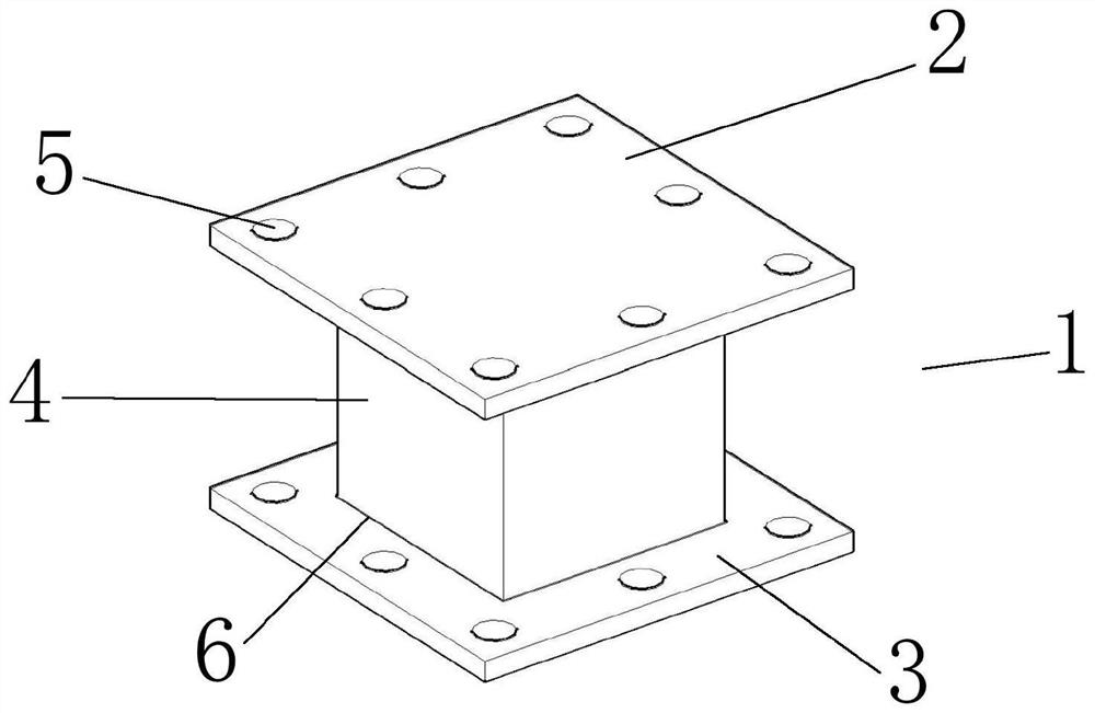
[0043] Further, the vertical connection device 1 includes a vertical node connection plate 2, a column connection plate 3 and a short concrete-filled...
specific Embodiment approach 2
[0047] A prefabricated reinforced concrete beam-column node 9, including vertical longitudinal reinforcement 10, transverse longitudinal reinforcement 12 and at least two adjacent beam unit connection ends 11, the vertical longitudinal reinforcement 10 can pass through the installation hole of the vertical connection device 1 5 and connected with the vertical node connection plate 2, so that the top or bottom surface of the fabricated reinforced concrete node 9 coincides with the vertical node connection plate 2; the transverse longitudinal reinforcement 12 can pass through the installation hole 22 of the transverse connection device 18 and connect with the transverse node The connecting plate 19 is connected so that the beam element connecting end 11 and the transverse node connecting plate 19 coincide (such as figure 1 , 2 ).
[0048] Further, when installing the vertical connection device 1, the extension length of the vertical longitudinal reinforcement 10 of the node and...
specific Embodiment approach 3
[0054] A prefabricated reinforced concrete beam-column node 9, including vertical longitudinal reinforcement 10, transverse longitudinal reinforcement 12 and at least two adjacent beam unit connection ends 11, the vertical longitudinal reinforcement 10 can pass through the installation hole of the vertical connection device 1 5 and connected with the vertical node connection plate 2, so that the top or bottom surface of the fabricated reinforced concrete node 9 coincides with the vertical node connection plate 2; the transverse longitudinal reinforcement 12 can pass through the installation hole 22 of the transverse connection device 18 and connect with the transverse node The connecting plate 19 is connected so that the beam element connecting end 11 and the transverse node connecting plate 19 coincide (such as figure 1 , 2 ).
[0055] Further, the vertical node connecting plate 2 fits with the node 9 (top surface or bottom surface) or the prefabricated floor unit 15 install...
PUM
 Abstract
Description
Claims
Application Information
 - Generate Ideas
- Intellectual Property
- Life Sciences
- Materials
- Tech Scout
- Unparalleled Data Quality
- Higher Quality Content
- 60% Fewer Hallucinations
Browse by: Latest US Patents, China's latest patents, Technical Efficacy Thesaurus, Application Domain, Technology Topic, Popular Technical Reports.
© 2025 PatSnap. All rights reserved.Legal|Privacy policy|Modern Slavery Act Transparency Statement|Sitemap|About US| Contact US: help@patsnap.com