Supporting platform for mounting of steel structure industrial factory building

A technology for industrial workshops and supporting platforms, which is applied to the preparation of pillars, building structures, and building components on site, and can solve the problems of wasting time for lifting I-beams

Inactive Publication Date: 2021-04-06
杨明芹
View PDF5 Cites 2 Cited by
  • Summary
  • Abstract
  • Description
  • Claims
  • Application Information

AI Technical Summary

Problems solved by technology

[0002] By erecting the I-beams according to the established construction standards, it is possible to build a steel structure factory building skeleton, and the steel structure factory building has the advantages of light weight, high strength, large span, short construction period, low investment cost, and easy building relocation. Convenience, recycling and pollution-free features make the steel structu

Method used


Image

  • Supporting platform for mounting of steel structure industrial factory building
  • Supporting platform for mounting of steel structure industrial factory building
  • Supporting platform for mounting of steel structure industrial factory building

Examples


Embodiment 1

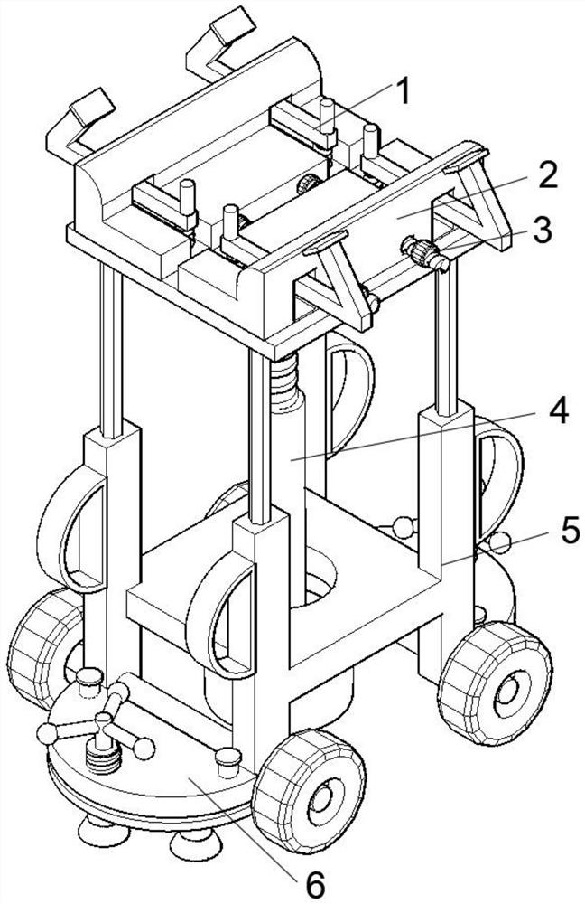
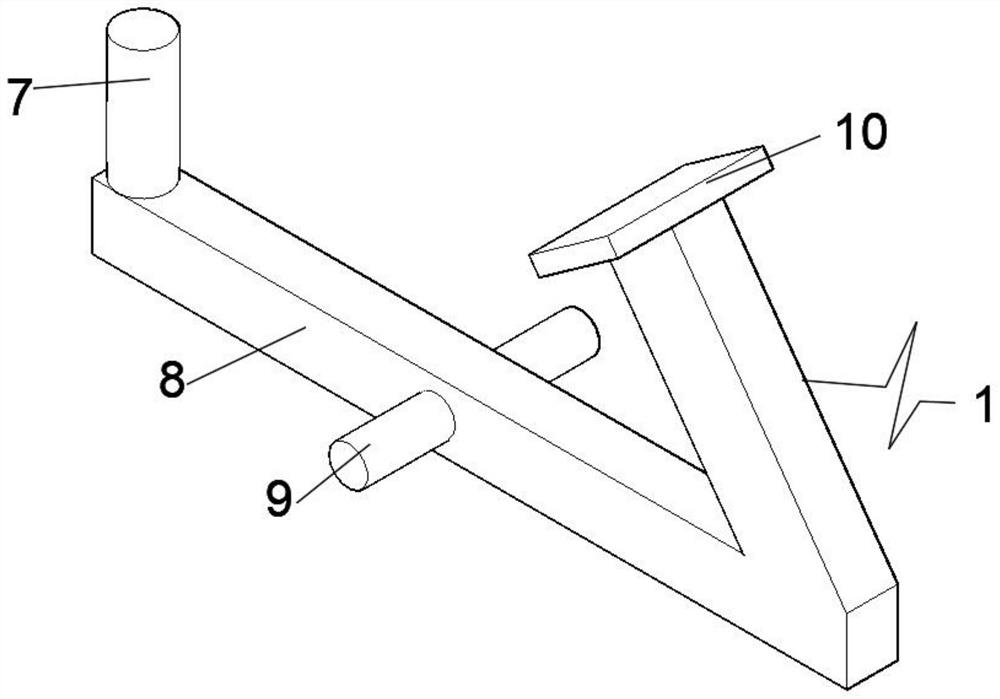
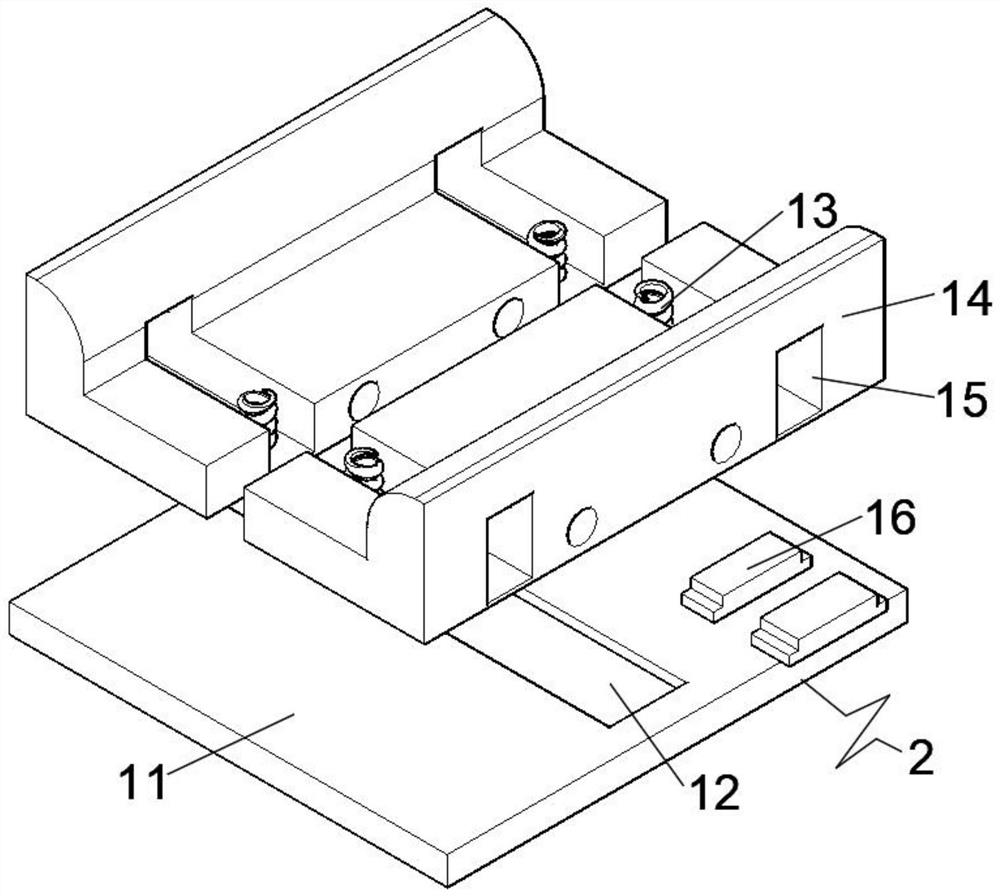
[0029] see Figure 1-7, an embodiment provided by the present invention: a support platform for installation of a steel structure industrial plant, including a mobile chassis 5, the interior of the mobile chassis 5 is fixedly connected with a transmission device 4, and the top of the transmission device 4 is fixedly connected with an adjustment base 2, Both sides of the adjustment base 2 are slidingly inserted into the limit device 3, and the internal symmetrical rotation of the adjustment base 2 is connected with a clamping rod 1, and the two ends of the mobile chassis 5 are fixedly welded with a stable limiter 6. The clamping rod 1 includes the first The supporting column 7, the first limiting rod 8, the first rotating rod 9 and the first extruding plate 10, the first supporting column 7 is fixedly welded on one end of the first limiting rod 8, and the first extruding plate 10 is fixedly welded On the other end of the first limiting rod 8, the first rotating rod 9 is symmetr...

Embodiment 2

[0032] On the basis of Example 1, such as Figure 8 As shown, the clamping rod 1 includes a second extruding plate 32, a second limiting rod 33, a second rotating rod 34, a gasket 35 and a second support column 36, and the second extruding plate 32 is fixedly connected to the second limiting rod. On one end of the position rod 33, the second support column 36 is fixedly connected on the other end of the second position limit rod 33, the gasket 35 is fixedly connected to the top of the second support column 36, and the second rotating rod 34 is symmetrically fixedly connected to the second On the side end of the limiting rod 33 , the material of the gasket 35 is wear-resistant rubber, and the second extruding plate 32 is provided with anti-slip lines.

[0033] In this embodiment, anti-slip lines are provided on the second extrusion plate 32 during implementation, so that the friction force when clamping the I-beam can be improved, and the gasket 35 is fixedly connected to the t...


PUM


Abstract

The invention discloses a supporting platform for mounting of a steel structure industrial factory building. The platform comprises a movable chassis; a transmission device is fixedly connected inside the movable chassis; an adjusting base is fixedly connected to the top end of the transmission device; limiting devices are slidably inserted into the two sides of the adjusting base; clamping rods are symmetrically and rotationally connected inside the adjusting base; stable limiters are fixedly welded to the two ends of the movable chassis; each clamping rod comprises a first supporting column, a first limiting rod, first rotating rods and a first extrusion plate; each first supporting column is fixedly welded to one end of the corresponding first limiting rod; each first extrusion plate is fixedly welded to the other end of the corresponding first limiting rod; and the first rotating rods are symmetrically and fixedly connected to the side ends of the corresponding first limiting rod. The platform is lifted to a specified height by the transmission device, and the clamping rods and the adjusting base are cooperatively fixed, so that the waiting time of a crane can be shortened and the working efficiency of hoisting is improved.

Description

technical field [0001] The invention relates to the technical field of factory building installation, in particular to a support platform for steel structure industrial factory building installation. Background technique [0002] By erecting the I-beam according to the established construction standards, it is possible to build a steel structure factory building skeleton, and the steel structure factory building has the advantages of light weight, high strength, large span, short construction period, low investment cost, and easy building relocation. Convenience, recycling and pollution-free features make steel-structured workshops popular with the public. When erecting I-beams, they need to be lifted to a specified height by a crane, and then the beams and base columns are welded at the top by personnel. Here During the construction process, the crane cannot move all the time, which wastes the time for the crane to lift the I-beam again. Therefore, a kind of equipment is ne...

Claims


Application Information

Patent Timeline
IPC IPC(8): E04G21/16E04G21/14E04G25/06E04G25/04
CPCE04G21/14E04G21/162E04G25/04E04G25/06
Inventor 杨明芹
Owner 杨明芹
Why Eureka
Try Eureka