PCB for frequency conversion of operating lamp

A PCB board and surgical lamp technology, applied in the field of surgical lamps, can solve the problems of increasing PCB board material use process and installation process, PCB board damage, scrapping, etc., to achieve the effect of convenient and flexible movement, avoiding serious damage, and avoiding drilling operations

Pending Publication Date: 2021-04-06
安徽广德威正光电科技有限公司
View PDF5 Cites 0 Cited by
  • Summary
  • Abstract
  • Description
  • Claims
  • Application Information

AI Technical Summary

Problems solved by technology

[0005] The technical problem to be solved by the present invention is: when installing the PCB board for frequency conversion of surgical lights, it is inevitable to punch holes in the PCB board. Once the punching ope

Method used


Image

  • PCB for frequency conversion of operating lamp
  • PCB for frequency conversion of operating lamp
  • PCB for frequency conversion of operating lamp

Examples


Embodiment 1

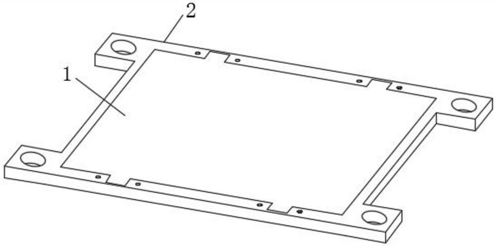
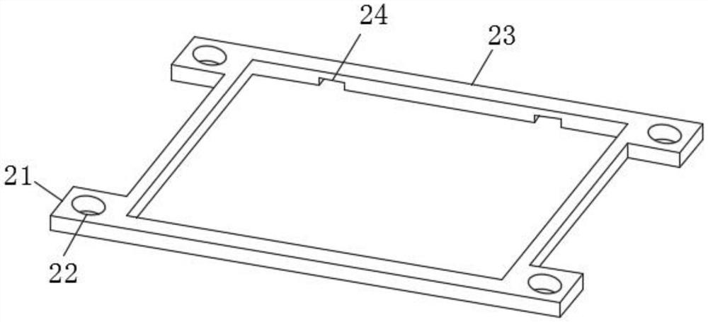
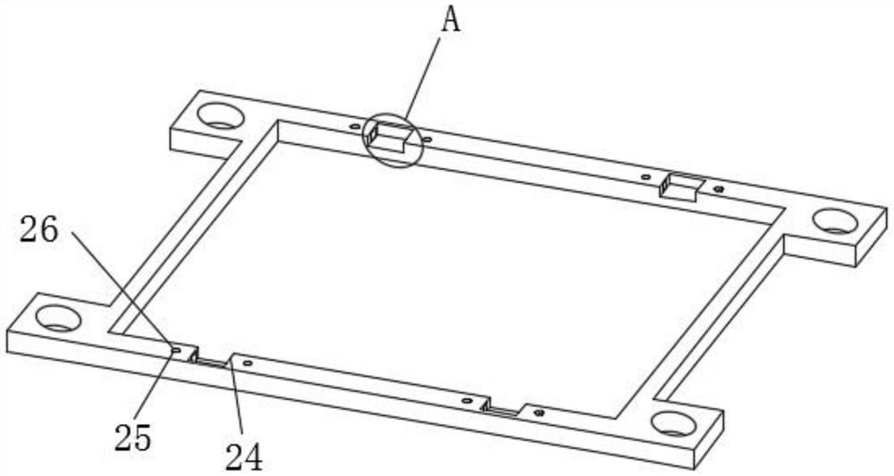
[0035] see Figure 1-7 As shown, a PCB board for frequency conversion of operating lights includes a PCB board body 1 and a disassembly assembly 2, and the disassembly assembly 2 includes a mounting part 21, a mounting hole 22, a mounting frame 23, a clamping groove 24, and a cylindrical hole 25 , rotating rod 26, clamping plate 27, rectangular movable groove 28, rectangular movable rod 29, rectangular threaded groove 291 and threaded mounting ring 292;

[0036] The outside of the PCB board body 1 is provided with a mounting frame 23, and the inner wall of the mounting frame 23 is provided with four sets of clamping grooves 24, and the two side walls of the four sets of clamping grooves 24 are symmetrically installed with clamping plates 27. The inside of the installation frame 23 is provided with a rectangular movable groove 28, which is located on both sides of the clamping groove 24, and a rectangular movable rod 29 is installed inside the rectangular movable groove 28, and...

Embodiment 2

[0042] A PCB board for frequency conversion of an operating light, and the working steps of the PCB board for frequency conversion of the operating light are as follows:

[0043] Step 1: Open installation holes 22 in the installation part 21 on the installation frame 23, four sets of clamping slots 24 are provided on the inner side of the installation frame 23, rectangular movable slots 28 are opened symmetrically on both sides of the clamping slots 24, and then the rectangular movable slots 28 are opened in the rectangular movable slots. A rectangular threaded groove 291 is provided inside the rod 29, the threaded fixing ring is assembled in the rectangular threaded groove 291, the rectangular movable rod 29 is fixedly connected with the clamping plate 27, and finally the rectangular movable rod 29 is embedded in the rectangular movable groove 28, and the installation frame 23 is preliminary complete assembly;

[0044] Step 2, the staff screw the lower end of the rotating rod...


PUM


Abstract

The invention discloses a PCB for frequency conversion of an operating lamp. The PCB comprises a mounting frame, rotating rods, clamping plates, rectangular movable grooves, rectangular movable rods, rectangular threaded grooves and threaded mounting rings; the mounting frame is arranged on the outer side of a PCB body; the clamping plates are symmetrically mounted on the two side walls of four sets of clamping grooves; the rectangular movable grooves are formed in the mounting frame; the rectangular movable grooves are formed in the two sides of the clamping grooves; the rectangular movable rods are mounted in the rectangular movable grooves; the rectangular threaded grooves are formed in the rectangular movable rods; the threaded mounting rings are mounted in the rectangular threaded grooves in a meshed mode; and the rotating rods are mounted in the threaded mounting rings in a meshed mode. By adopting the PCB for frequency conversion of the operating lamp, the installation mode of the PCB for operating lamp frequency conversion is simplified; serious damage and even scrapping of the PCB due to punching misoperation are avoided; damage to the PCB is reduced; and the use procedure and the installation procedure of the PCB are simplified.

Description

technical field [0001] The invention belongs to the technical field of operating lamps, relates to PCB board technology, in particular to a PCB board for frequency conversion of operating lamps. Background technique [0002] Surgical lights can guarantee the lighting brightness of the operating room. Surgeons in the operating room must be able to accurately distinguish contours, colors and movements. Therefore, light intensity close to daylight quality is required, and the light intensity of at least 100,000 illuminance can be provided by the operating light. The maximum brightness of a single lamp can reach 150,000 illuminance, and the brightness of the surgical lamp can be adjusted steplessly. In case of failure during the operation, the spare bulb can be automatically switched for 0.3 seconds, so the surgical lamp can provide safe surgical lighting . The surgical lamp can meet the requirements of shadow-free lighting through the polygonal reflector. This reflective surfa...

Claims


Application Information

Patent Timeline
IPC IPC(8): F21V21/00F21V17/12F21V17/16F21W131/205
CPCF21V21/00F21V17/12F21V17/164F21W2131/205
Inventor 袁胜巧
Owner 安徽广德威正光电科技有限公司
Why Eureka
Try Eureka