Separated heat pipe system capable of adjusting flow resistance and using method

A separate heat pipe and flow resistance technology, which is applied in the field of heat pipes, can solve the problems of increased resistance along the pipe wall, fatigue of the pipe wall, and obstruction of the circulation of working fluid, etc., to achieve convenient disassembly, prolong service life, and maintain normal and stable operation Effect

Active Publication Date: 2021-04-06
SHANDONG UNIV
View PDF7 Cites 1 Cited by
  • Summary
  • Abstract
  • Description
  • Claims
  • Application Information

AI Technical Summary

Problems solved by technology

[0004] However, the separated heat pipe also has a certain heat transfer limit. The inventor found that under the condition of high heat flux density, the steam flow rate and condensate flow rate in the heat pipe increase, and the flow rate of the fluid increases, resulting in an increase in the resistance along the tube wall. , the circulation of the working fluid is b

Method used


Image

  • Separated heat pipe system capable of adjusting flow resistance and using method

Examples


Embodiment Construction

[0026] It should be noted that the following detailed description is exemplary and intended to provide further explanation of the present invention. Unless defined otherwise, all technical and scientific terms used herein have the same meaning as commonly understood by one of ordinary skill in the art to which this invention belongs.

[0027] It should be noted that the terminology used here is only for describing specific embodiments, and is not intended to limit exemplary embodiments according to the present invention. As used herein, unless the invention clearly states otherwise, the singular form is also intended to include the plural form. In addition, it should also be understood that when the terms "comprising" and / or "comprising" are used in this specification, their Indicate the presence of features, steps, operations, means, components and / or combinations thereof;

[0028] For the convenience of description, if the words "up", "down", "left" and "right" appear in th...


PUM


Abstract

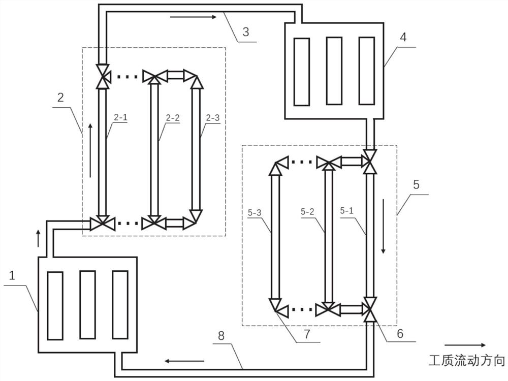
The invention discloses a separated heat pipe system capable of adjusting flow resistance and a using method thereof, solves the problem of failure of the heat pipe system due to increase of closing on-way resistance caused by increase of fluid flow rate in the heat pipe system, and has the advantages that on-way resistance adjustment can be realized, and an ascending pipe or a descending pipe is convenient to replace. According to the specific scheme, the separated heat pipe system capable of adjusting the flow resistance comprises an evaporator, a condenser, an ascending pipe component and a descending pipe component, the condenser is higher than the evaporator, one side of the evaporator and one side of the condenser are connected through the ascending pipe component, and the other side of the evaporator and the other side of the condenser are connected through the descending pipe component. The ascending pipe component and the descending pipe component respectively comprise a plurality of pipelines which are arranged in parallel and can be communicated, the pipelines of the ascending pipe component and the descending pipe component are connected through valves, the flow resistances of the pipelines in the ascending pipe component are different, and the flow resistances of the pipelines in the descending pipe component are different.

Description

technical field [0001] The invention relates to the field of heat pipes, in particular to a separate heat pipe system with adjustable flow resistance and its use method. Background technique [0002] The statements in this section merely provide background information related to the present invention and do not necessarily constitute prior art. [0003] Heat pipes are more and more widely used in electronic products and daily life. Due to the separability of the evaporator and condenser, the separated heat pipe has a wider range of applications than the traditional integral heat pipe. It can be applied to the situation where the heat source and the cold source are far apart, or the cold source and the heat source are located indoors and outdoors. At the same time, the hot and cold ends can exchange heat with different fluids, preventing the mutual leakage of the hot and cold ends. [0004] However, the separated heat pipe also has a certain heat transfer limit. The invento...

Claims


Application Information

Patent Timeline
IPC IPC(8): F28D15/02F28D15/04F28D15/06
CPCF28D15/0266F28D15/04F28D15/06
Inventor 孙锲江梦倩王硕霍禄平
Owner SHANDONG UNIV
Why Eureka
Try Eureka