Photoresist granularity testing device
A test device and photoresist technology, which is applied in the field of photoresist, can solve problems such as inaccurate test data and unstable flow, and achieve the effects of improving reliability and repeatability, improving test accuracy, and simplifying operations
- Summary
- Abstract
- Description
- Claims
- Application Information
AI Technical Summary
Problems solved by technology
Method used
Image
Examples
Embodiment 1
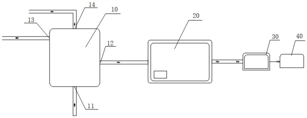
[0032] Such as figure 1 As shown, the present invention provides a photoresist particle size testing device, comprising, a head tank 10, connected with the photoresist production line for storing the photoresist to be tested; a particle analyzer 20, used to measure the photoresist to be tested Particle size; the bottom of the head tank 10 is provided with a feed port 11 connected to the pipeline of the photoresist production line; the side of the head tank 10 is provided with a discharge port 12 connected to the feed pipeline of the particle meter; the outlet of the particle meter 20 There is also a flow meter 30 for adjusting the photoresist flow parameters to be measured in the particle analyzer 20 at the end.
[0033] In this embodiment, the discharge port 12 is provided under the side of the elevated tank 10 to ensure that the photoresist to be measured flowing into the elevated tank flows stably into the particle analyzer 20 under the action of its own gravity.
[0034] ...
Embodiment 2
[0038] Such as figure 1 As shown, on the basis of the first embodiment, the top of the elevated tank 10 in this embodiment also has an air inlet 14 for inputting nitrogen.
[0039] Further, the air inlet 14 is connected with an air inlet device for delivering nitrogen gas into the elevated tank 10 .
[0040] When the photoresist liquid to be tested flows in the pipeline, tiny air bubbles will be generated due to the pressure difference of the pipeline. After passing through the particle analyzer, these small air bubbles will cause the instrument to report errors and affect the test results, so the test pipeline needs to be emptied.
[0041] Compared with the existing exhaust operation of opening a vent hole on the feed pipeline, when the operation is improper, the problem of photoresist leakage or pollution is prone to occur. In this embodiment, the air bubbles in the photoresist to be tested are discharged through the input of nitrogen gas through the air inlet 14 on the to...
Embodiment 3
[0044] On the basis of embodiment one or two, in this embodiment, an overflow port 13 is provided above the side of the elevated tank 10, for reclaiming the photoresist to be measured due to the large flow rate overflowing, the position of the overflow port 13 Higher than the discharge port 12 position.
[0045] Further, the overflow port 13 is connected with a storage tank for recovering overflowed photoresist to be tested through an overflow pipeline. In this embodiment, the photoresist to be measured flows into the particle analyzer through the discharge port 12, and the flow rate of the photoresist to be measured into the particle meter is adjusted and controlled by the gravity of the photoresist to be measured in the header tank 10 and the flow meter. , to keep its flow steady. The photoresist to be tested that is higher than the discharge port 12 flows into the storage tank through the overflow port 13 .
[0046] The photoresist particle size testing device of this emb...
PUM
 Abstract
Description
Claims
Application Information
 - R&D
- Intellectual Property
- Life Sciences
- Materials
- Tech Scout
- Unparalleled Data Quality
- Higher Quality Content
- 60% Fewer Hallucinations
Browse by: Latest US Patents, China's latest patents, Technical Efficacy Thesaurus, Application Domain, Technology Topic, Popular Technical Reports.
© 2025 PatSnap. All rights reserved.Legal|Privacy policy|Modern Slavery Act Transparency Statement|Sitemap|About US| Contact US: help@patsnap.com


