
Wind direction and wind speed monitoring device

A monitoring device and technology for wind direction and wind speed are applied in the field of measuring instruments, which can solve the problems of inability to monitor wind direction and wind speed, and achieve the effect of strong anti-electromagnetic interference ability and long-distance monitoring.

Pending Publication Date: 2021-04-06
NORTHEAST FORESTRY UNIVERSITY
View PDF0 Cites 0 Cited by
  • Summary
  • Abstract
  • Description
  • Claims
  • Application Information

AI Technical Summary

Problems solved by technology

However, most of these anemometers measure wind direction and speed directly or indirectly through the correspondence between electrical signals, wind direction and wind speed, and cannot be applied to wind direction and speed monitoring in specific environments such as flammable and explosive.

Method used


Image

  • Wind direction and wind speed monitoring device
  • Wind direction and wind speed monitoring device

Examples


Embodiment Construction

[0016] The present invention will be further described below in conjunction with accompanying drawing and specific embodiment, but they are not limitation of the present invention:

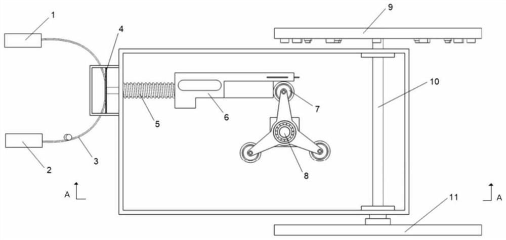
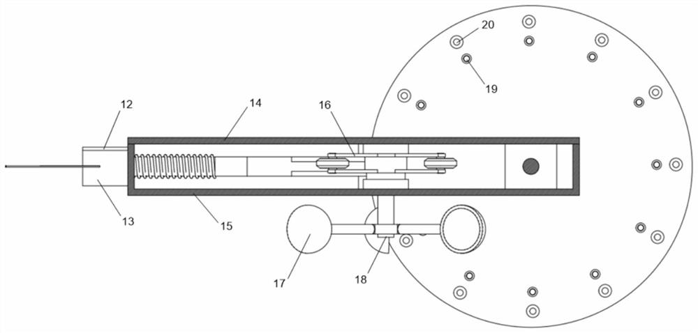
[0017] Such as figure 1 with figure 2 As shown, a wind direction and wind speed monitoring device includes a light source 1, a photoelectric transistor 2, an optical fiber 3, a simply supported beam 4, a spring 5, a force transmission block 6, a rotating wheel 7, a first rotating shaft 8, an upper rotating disk 9, and a second rotating shaft 10. Lower turntable 11, fiber optic cover 12, fiber optic cover 13, cover plate 14, box body 15, rotating member 16, wind cup 17, wind cup connecting screw 18, light transmitter 19, light receiver 20, the cover The plate 14 is connected with the box body 15 by screws, and the box body 15 is processed with through holes; the cover plate 14 and the box body 15 are all provided with slide grooves; the first rotating shaft 8 is processed with a flat keyway; The...


PUM


Abstract

The invention discloses a wind direction and wind speed monitoring device, and belongs to the field of wind direction and wind speed measuring instruments. A first rotating shaft is connected with a cover plate and a box body through bearings and penetrates through a through hole of the box body to be connected with a wind cup; a second rotating shaft is respectively connected with the box body, an upper turntable and a lower turntable through bearings, and the upper turntable is provided with a plurality of light emitters and light receivers which are circumferentially and uniformly distributed for wind direction monitoring; a plurality of rotating wheels are uniformly distributed on the circumference of the rotating piece and are connected with the first rotating shaft through flat keys; a sliding sheet of a force transmission block is matched with the cover plate and a sliding groove of the box body; the tail end of the force transmission block and a spring are connected with the box body, and the tail end of the force transmission block is fixed to the center of a simply supported beam; an optical fiber processed with a light leakage area is adhered to the simply supported beam through flexible glue; and two ends of the optical fiber are respectively connected with a light source and a photoelectric triode. According to the invention, remote wind direction and wind speed monitoring is realized, the structure is simple, and wind direction and wind speed monitoring can be realized in strong electromagnetic interference and flammable and combustible environments.

Description

technical field [0001] The invention relates to a measuring instrument, in particular to a wind direction and wind speed monitoring device. Background technique [0002] Most wind direction anemometers on the market measure wind speed through rotating parts such as wind cups and propellers, and measure wind direction through wind vanes. However, most of these anemometers measure wind direction and speed directly or indirectly through the correspondence between electrical signals, wind direction and wind speed, and cannot be applied to wind direction and speed monitoring in specific environments such as inflammable and explosive environments. Optical fiber sensing technology has the advantages of high sensitivity, good linearity, anti-magnetic and explosion-proof, and strong adaptability to the environment. Therefore, the use of optical fiber sensing technology for wind direction and speed monitoring can overcome the shortcomings of current wind direction and anemometers. C...

Claims


Application Information

Patent Timeline
IPC IPC(8): G01P5/26G01P13/02
CPCG01P5/26G01P13/02
Inventor 支冠华狄海廷辛颖安立华
Owner NORTHEAST FORESTRY UNIVERSITY
Learn More