Corn harvesting device

A harvesting device and corn technology, applied in threshing equipment, applications, agricultural machinery and tools, etc., can solve problems such as poor threshing effect and achieve good threshing effect

Active Publication Date: 2021-04-09
奉节县鑫桥农业开发有限公司
View PDF5 Cites 0 Cited by
  • Summary
  • Abstract
  • Description
  • Claims
  • Application Information

AI Technical Summary

Problems solved by technology

[0003] The purpose of the present invention is to solve the shortcomings of poor threshing effect in the prior art, and propose a corn harvesting device

Method used


Image

  • Corn harvesting device
  • Corn harvesting device
  • Corn harvesting device

Examples


Embodiment 1

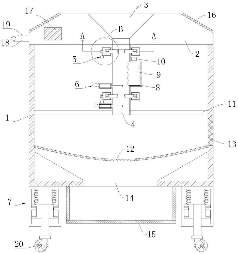
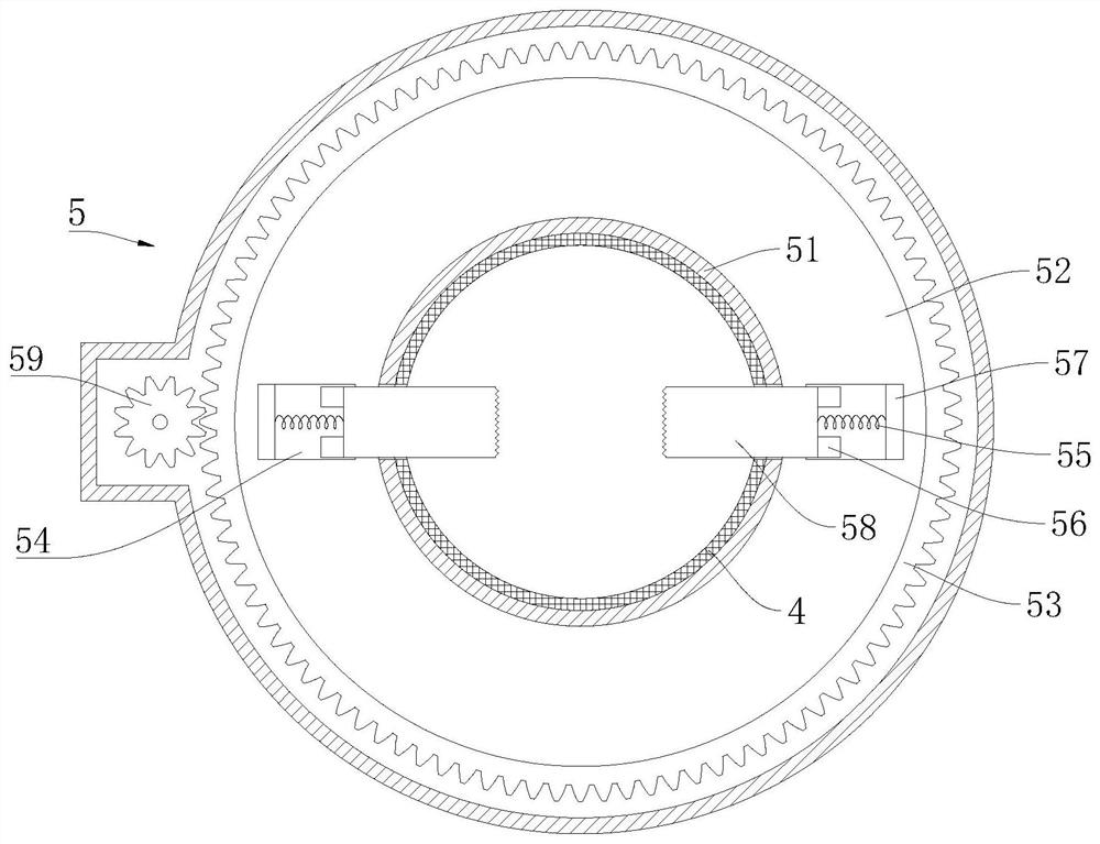
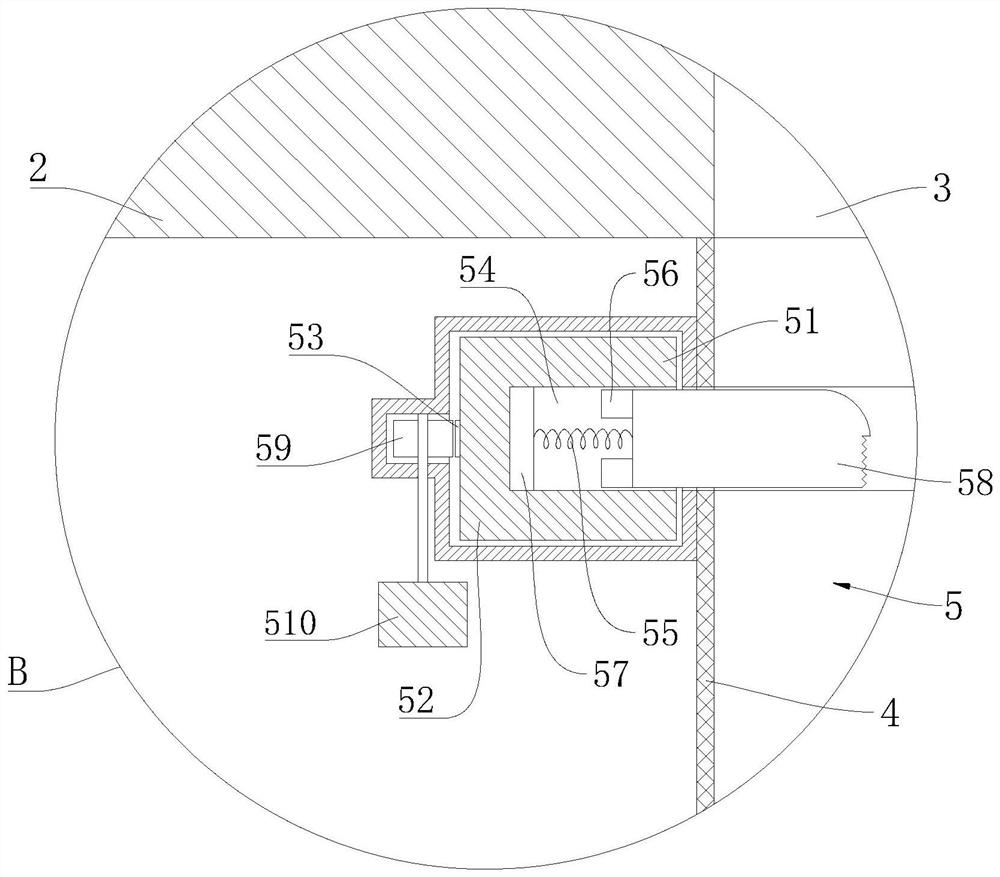
[0023] refer to Figure 1-5 , a corn harvesting device, comprising an outer box body 1, a fixed cover on the upper end of the outer box body 1 is provided with a box cover 2, a handle 18 is fixedly installed on one side of the box cover 2, a feeding port 3 is opened in the middle part of the box cover 2, and the box cover 2. A connecting pipe 4 is fixedly installed in the middle of the lower surface. When the corn is put into the feeding port 3, the corn will enter the connecting pipe 4. A clamping piece 5 is fixedly installed above the outer surface of the connecting pipe 4. The middle part of the outer surface of the connecting pipe 4 is A fixed shell 8 is fixedly installed on the side, and a first micromotor 10 is fixedly installed above the fixed shell 8. A threshing roller 9 is fixedly installed at the lower end of the control output of the first micromotor 10. The threshing roller 9 is arranged inside the fixed shell 8. The first micromotor 10 start-up will drive the thr...

Embodiment 2

[0031] refer to figure 1 , as another preferred embodiment of the present invention, on the basis of Embodiment 1, a solar cell panel 16 is fixedly installed on the outer side of the upper end surface of the case cover 2, and a storage battery 17 is fixedly installed on the inner side of the case cover 2, and the solar cell panel 16 passes through The wire is electrically connected to an inverter, and the inverter is electrically connected to the battery 17. A control panel 19 is fixedly installed on the upper end of the handle 18. The control panel 19 is electrically connected to the battery 17 through a wire, and the control panel 19 is also connected to the second battery through a wire. A micromotor 10, the second micromotor 510, the third micromotor 68 and the electromagnet 57 are electrically connected, and there is an angle between the length direction of the solar panel 16 and the horizontal plane, so that the solar panel 16 is more convenient to receive Under sunlight...


PUM


Abstract

The invention relates to the technical field of corn harvesting, in particular to a corn harvesting device, which comprises an outer box body. A box cover fixedly covers the upper end of the outer box body, a handle is fixedly installed on one side of the box cover, a feeding port is formed in the middle of the box cover, and a communicating pipe is fixedly installed in the middle of the lower surface of the box cover. A clamping piece is fixedly installed above the outer side surface of the communicating pipe, a fixing shell is fixedly installed on one side of the middle of the outer side surface of the communicating pipe, a first micro motor is fixedly installed above the fixing shell, a threshing roller is fixedly installed at the lower end of a control output of the first micro motor, and the threshing roller is arranged on the inner side of the fixing shell. A partition board is fixedly installed on the surface of the inner wall of the outer box body and located below the communicating pipe. The corn harvesting device has the advantages that corn can be conveniently threshed, good threshing effects can be realized, and the corn threshing device is worthy of popularization.

Description

technical field [0001] The invention relates to the technical field of corn harvesting, in particular to a corn harvesting device. Background technique [0002] Corn ranks first among the three major grains. my country is a major producer and consumer of corn. The sown area, total output, and consumption are second only to the United States, ranking second in the world. Compared with rice, corn and wheat are more widely used grain varieties, and they are both food, feed and industrial raw materials. At present, there are large-scale corn threshers used in agricultural production on the market, but the existing corn threshers cannot perform relatively complete threshing of corn during production and use, and the threshing effect will not be very good. Contents of the invention [0003] The purpose of the present invention is to solve the shortcomings of poor threshing effect in the prior art, and propose a corn harvesting device. [0004] In order to achieve the above obj...

Claims


Application Information

Patent Timeline
IPC IPC(8): A01F11/06A01F12/00
CPCA01F11/06A01F12/00
Inventor 林桥
Owner 奉节县鑫桥农业开发有限公司
Why Eureka
Try Eureka