Printing protective fingerstall with ventilation function

A finger cover and functional technology, applied in the field of printing protective finger cover, can solve the problems of finger burns, easy touch, and easy sweating of fingers, and achieve the effect of avoiding imprints

Pending Publication Date: 2021-04-09
卢发均
View PDF0 Cites 0 Cited by
  • Summary
  • Abstract
  • Description
  • Claims
  • Application Information

AI Technical Summary

Problems solved by technology

[0002] During the printing process, due to the process of picking up materials, the fingers are easy to touch the printing part of the product that is not yet dry, leaving fingerprints on the printing part, which is not conducive to subsequent printing. Often such products, personnel need to bring Finger cot operation, at the same time, the printed products just out of the printing machine have a certain high temperature, which may cause burns to the fingers of the personnel and affect the production operation of the personnel.
After putting on the finger cots, the gloves are not airtight and have poor heat dissipation effect, which makes the fingers easy to sweat, and the personnel feel bad when using them

Method used


Image

  • Printing protective fingerstall with ventilation function
  • Printing protective fingerstall with ventilation function
  • Printing protective fingerstall with ventilation function

Examples


Embodiment Construction

[0029] The following will clearly and completely describe the technical solutions in the embodiments of the present invention with reference to the accompanying drawings in the embodiments of the present invention. Obviously, the described embodiments are only some, not all, embodiments of the present invention.

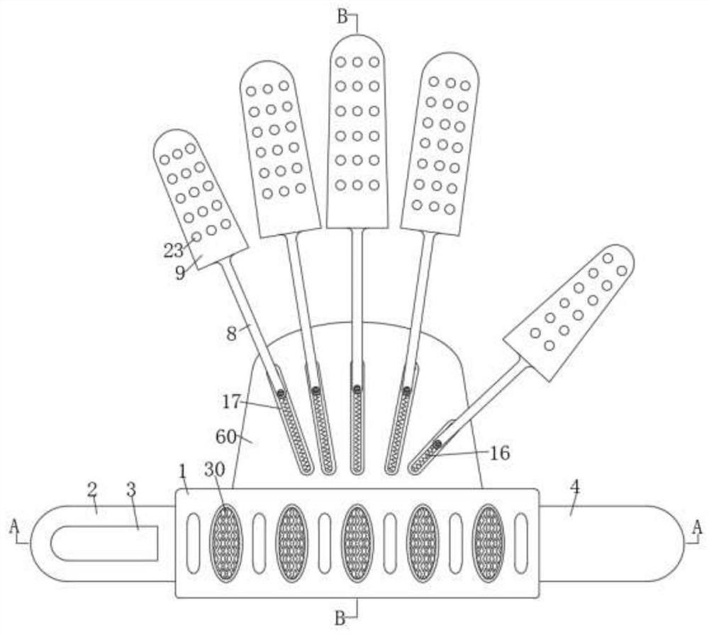
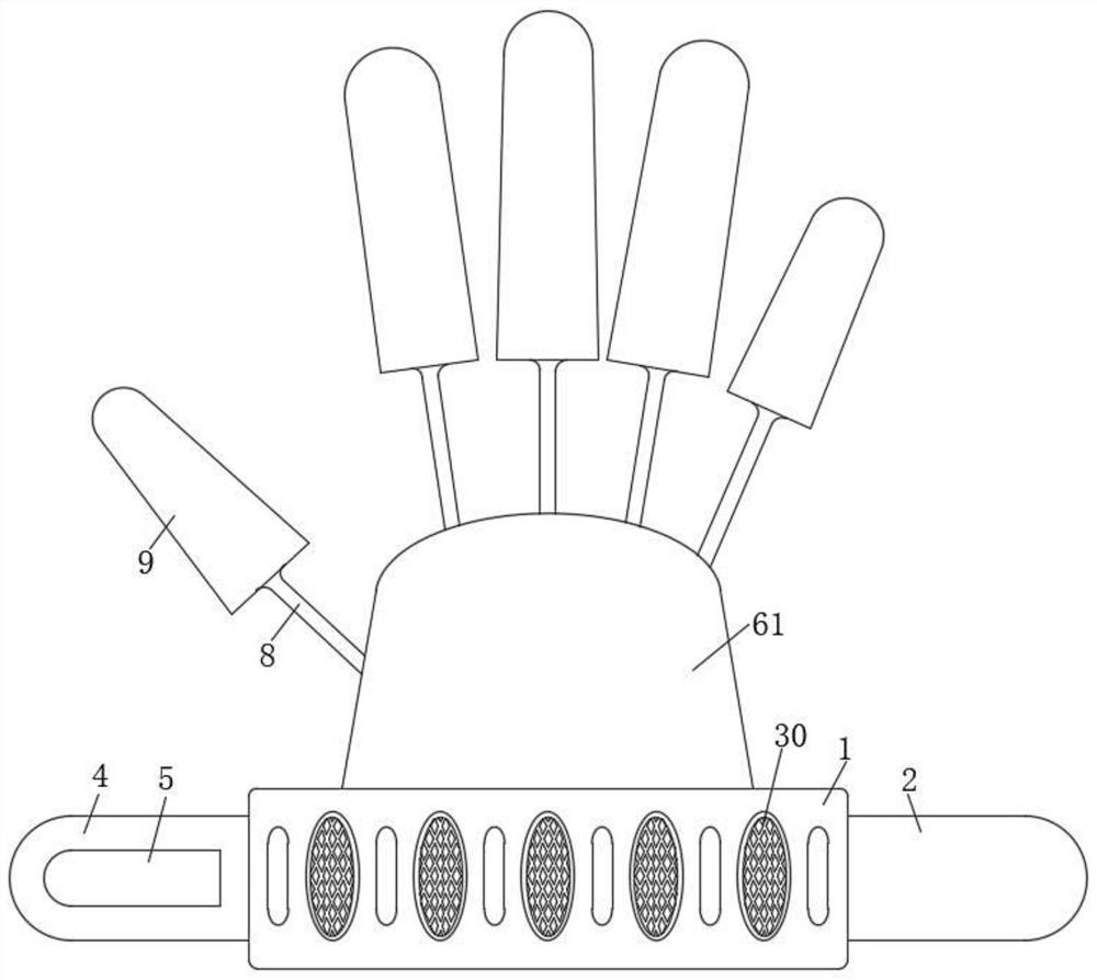
[0030] refer to Figure 1-10 , a printed protective finger cot with breathable function, comprising a wristband 1, one end of the wristband 1 is connected with a first binding strip 2, one side of the first binding strip 2 is provided with a loop strip 3, the wristband The end of the strip 1 away from the first binding strip 2 is connected with a second binding strip 4, and one side of the second binding strip 4 is provided with a hook strip 5 matching the pile loop strip 3, and the inside of the wrist support strip 1 is evenly filled. The buffer sponge strip 29 is installed, and the wristband 1 between two adjacent buffer sponge strips 29 is provided with a fourth t...


PUM


Abstract

The invention relates to the technical field of protective fingerstalls, in particular to a printed protective fingerstall with a ventilation function, which comprises a wrist strap, one end of the wrist strap is connected with a first binding strip, one side of the first binding strip is provided with a pile loop strip, and one end of the wrist strap far away from the first binding strip is connected with a second binding strip; a hook strip matched with the pile loop strip is arranged on one side of the second binding strip, a connecting cloth piece is arranged on the side, close to the fingers, of the wrist strap, five mounting columns are arranged on the side, away from the hand back, of the connecting cloth piece, and the outer sides of the five mounting columns are sleeved with first connecting strips; the ends, away from the mounting column, of the first connecting strips are connected with outer finger sleeves matched with the five fingers respectively, protective woven sleeves are arranged in the five outer finger sleeves respectively, arc-shaped supporting plates are evenly connected to insertion openings of the inner finger sleeves, and elastic connecting ropes are arranged between the adjacent arc-shaped supporting plates for fixed connection. By means of the finterstall, the fingers of an operator can be prevented from being scalded by printed products, and meanwhile, the protective fingerstalls facilitate heat dissipation and are not prone to sliding off.

Description

technical field [0001] The invention relates to the technical field of protective finger cots, in particular to a printed protective finger cot with a breathable function. Background technique [0002] During the printing process, due to the process of picking up materials, the fingers are easy to touch the printing part of the product that has not yet dried out, leaving fingerprints on the printing part, which is not conducive to subsequent printing. Often such products, personnel need to bring Finger cot operation, at the same time, the printed products just out of the printing machine have a certain high temperature, which may cause burns to the fingers of personnel, and affect the production operation of personnel. After putting on the finger cots, the airtight heat dissipation effect of the gloves is not good, which makes the fingers easy to sweat, and the personnel feel bad when using them. Contents of the invention [0003] The purpose of the present invention is t...

Claims


Application Information

Patent Timeline
Patent Type & Authority Applications(China)
IPC IPC(8): A41D13/08A41D27/00A41D27/28A41D31/02A41D31/04
CPCA41D13/087A41D13/088A41D27/00A41D27/28A41D31/02A41D2400/82A41D2500/20A41D2600/20A41D31/04
Inventor 卢发均
Owner 卢发均
Why Eureka
Try Eureka