
Fiber solid waste collection and treatment equipment

A solid waste and treatment equipment technology, applied in cleaning equipment, recycling technology, vacuum cleaners, etc., can solve the problems of broom cleaning troubles, dust suction pipes are not easy to block, bend, and block, so as to avoid direct contact, reduce labor intensity, Effect of improving collection efficiency

Active Publication Date: 2021-04-09
寿光市银河聚酯胎有限公司
View PDF5 Cites 3 Cited by
  • Summary
  • Abstract
  • Description
  • Claims
  • Application Information

AI Technical Summary

Problems solved by technology

[0004] In order to overcome the disadvantages of using a broom to clean the fiber waste, the fiber waste is easy to adhere to the broom, and the broom cleaning is troublesome, and the ordinary vacuum cleaner is prone to bending and clogging due to the suction pipe. The technical problem to be solved by the invention is to provide A kind of dust suction pipe is not easy to block and bend, and the fiber waste in the dust storage tank is taken out, which is a simple fiber solid waste collection and treatment equipment

Method used


Image

  • Fiber solid waste collection and treatment equipment
  • Fiber solid waste collection and treatment equipment
  • Fiber solid waste collection and treatment equipment

Examples


Embodiment 1

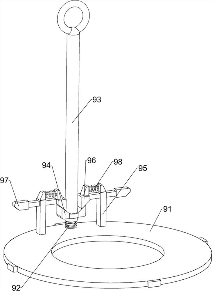
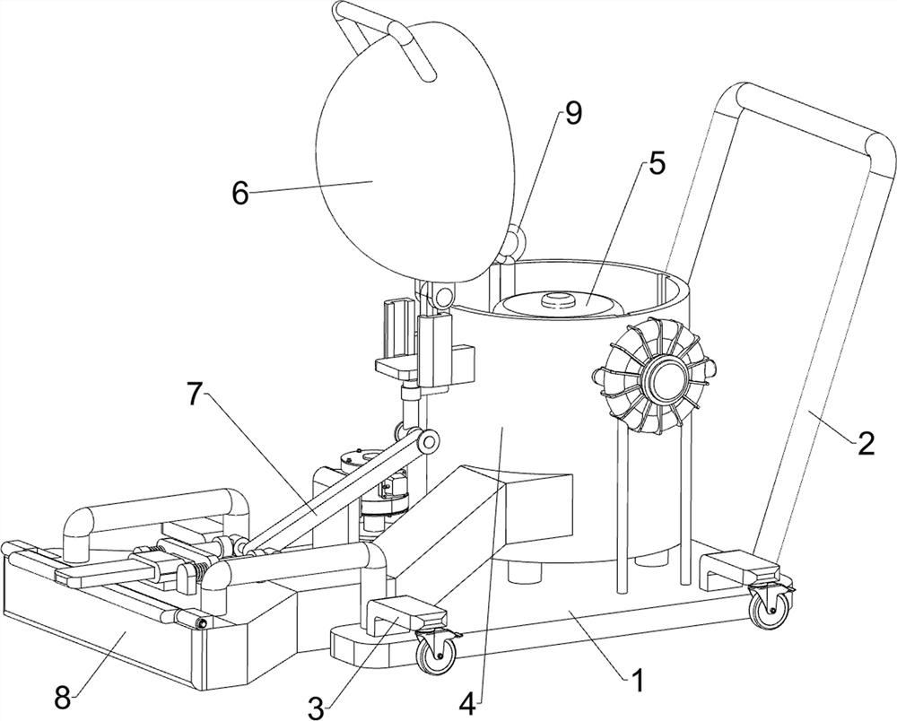
[0026]Fiber solid waste collection processing equipment, such asFigure 1 to 3As shown, including the bottom plate 1, the hand push rod 2, the wheel frame 3, the wind suction mechanism 4, the collecting mechanism 5, and the barrel cover mechanism 6, and the top right side of the bottom plate 1 is connected to the top of the bottom plate 2, the bottom plate 1 top The wheel frame 3 is connected, and the wind absorbing mechanism 4 is attached to the middle of the bottom plate 1, and the bottom plate 1 is connected between the bottom plate 1 and the wind absorbing mechanism 4, and the winding mechanism 4 is connected to the wind suction mechanism 4.

[0027]The wind absorbing mechanism 4 includes a support post 41, a collection tub 42, a drawing conduit 43, a fixing frame 44, a winder 45, and a support frame 46, and four support columns 41 are connected in the middle of the bottom plate 1, and four support column 41 top. The collected tub 42 is connected between the collected tub 42, and th...

Embodiment 2

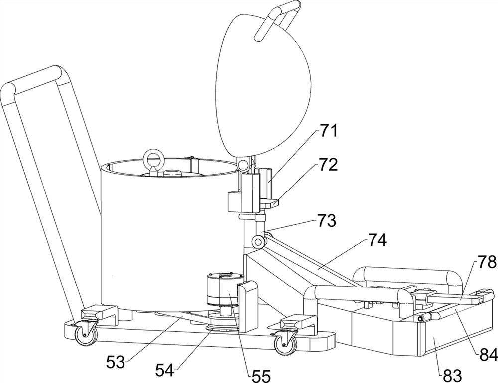
[0032]On the basis of Example 1, such asimage 3 withFigure 5 As shown, there is a baffle mechanism 8, and the baffle mechanism 8 includes a mount 81, a scroll spring 82, a movable baffle 83, and a bump 84, and the front and rear ends of the absorbing conduit 43 are connected to the mount 81. The movable baffle 83 of the mounting seat 81 on both sides is rotated between the moving absorbent pipe 43, and the active baffle 83 is connected to the movable block 83 and the movable plate 83 and the mounting seat 81 are connected to the scroll spring. 82.

[0033]When the fiber waste is not required, the inlet of the active baffle 83 blocks the absorbent conduit 43, so that the fiber waste in the collection tub 42 can be avoided. Open the active baffle 83 cover when collecting fiber waste.

Embodiment 3

[0035]On the basis of Example 2, such asimage 3 withFigure 5 As shown, there is also a linkage mechanism 7, the linkage mechanism 7 includes a guide rail 71, a sliding push plate 72, a first rod 73, a link 74, a second rod 75, a first guide sleeve 76, a second guide sleeve 77, the push rod 78, the fixing block 79 and the first reset spring 710, the upper portion of the collecting tub 42 is connected to the rail holder 71, the guide rails 71 slidely connected to the sliding push plate 72, the bottom of the sliding push plate 72 is connected. The first rod 73, the top left side of the top of the suction conduit 43 is connected to the two first guide sleeve 76 and two fixed blocks 79, and the first guide sleeve 76 is located on the right side of the fixed block 79, the first guide sleeve 76 sliding type The second rod 75 is connected to the second rod 75, and the upper right end of the second rod 75 is hinged between the bottom end of the first hose 73, and the connecting rod 74 is con...


PUM


Abstract

The invention relates to treatment equipment, and particularly relates to fiber solid waste collection and treatment equipment. The technical problem to be solved by the invention is to provide the fiber solid waste collection and treatment equipment with the advantages that a dust collection pipeline is not easy to block and bend, and fiber waste in a dust storage cylinder is easy to take out. In order to solve the technical problem, the invention provides the fiber solid waste collection and treatment equipment which comprises a bottom plate, a hand push rod, wheel frames, a wind power material suction mechanism, a collection mechanism and a barrel cover mechanism, wherein the hand push rod is connected to the right side of the top of the bottom plate, the wheel frames are connected to the four corners of the top of the bottom plate correspondingly, the wind power material suction mechanism is installed in the middle of the top of the bottom plate, the collection mechanism is connected between the bottom plate and the wind power material suction mechanism, and the barrel cover mechanism is connected to the wind power material suction mechanism. The fiber solid waste can be conveniently collected through the collection mechanism and the wind power material suction mechanism, manual sweeping and collecting are not needed, and fibers do not need to be wound manually.

Description

Technical field[0001]The present invention relates to a processing apparatus, and more particularly to a fiber solid waste collection processing apparatus.Background technique[0002]In the production workshop of the textile factory, there is a need to drop some fiber waste on the ground, so it is necessary to clean the fiber waste on the floor surface. Currently, the cleaning of fiber waste is usually artificial scan to clean the fiber waste, but because the fiber waste is easy. At the adhesion, there is a need for frequent cleaning of the scan, time-consuming, and some through the vacuum cleaner for cleaning the fiber waste. Because the vacuum cleaner is a complete pipeline, the pipeline is fine, the pipeline is not only easy to appear Bend, and it is easy to cause clogging, and the troubles of operating when the fiber waste in the reservoir is taken out, directly affecting the collection efficiency of fiber solid waste.Inventive content[0003](1) Technical issues to be solved[0004]I...

Claims


Application Information

Patent Timeline
IPC IPC(8): A47L5/32A47L9/00A47L9/14
CPCA47L5/32A47L9/1409A47L9/00Y02W30/66
Inventor 黄健浩
Owner 寿光市银河聚酯胎有限公司
Learn More