Spraying device for electromechanical equipment part machining

A technology of electromechanical equipment and spraying equipment, applied in spraying equipment, spray booths, etc., can solve problems such as uneven layer thickness

Active Publication Date: 2021-04-09
佛山市顺德区豫锐涂装设备有限公司
View PDF12 Cites 0 Cited by
  • Summary
  • Abstract
  • Description
  • Claims
  • Application Information

AI Technical Summary

Problems solved by technology

[0002] During the processing of parts of electromechanical equipment, many parts need to be sprayed and coated, but the existing spraying devices are fixed, and the nozzle part of some spraying devices can be moved to improve the unifor

Method used


Image

  • Spraying device for electromechanical equipment part machining
  • Spraying device for electromechanical equipment part machining
  • Spraying device for electromechanical equipment part machining

Examples


Embodiment 1

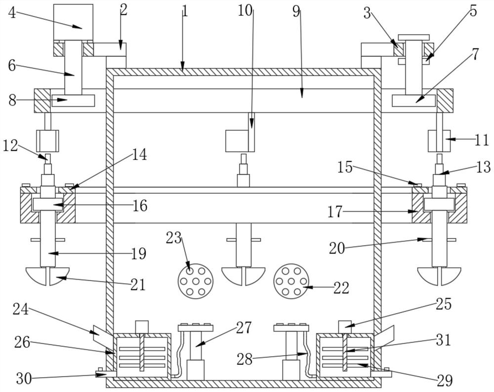
[0022] see Figure 1-4 , the present embodiment provides a kind of spraying device for the processing of mechanical and electrical equipment parts, including a processing box 1, and a spraying assembly is arranged in the processing box 1, and the spraying assembly includes respectively arranged in the processing box 1 Some spraying disks 22 on the side and up and down positions, some spraying heads 23 are arranged on the spraying disk 22, and a paint box 26 is also provided and useful On the conveying hose 28 connecting the two, a driving assembly, an intermediate assembly and a suspension assembly are also provided, and the two ends of the driving assembly and the intermediate assembly are respectively located outside the two sides of the processing box 1, and the driving assembly includes The driven chainring 7, the driving chainring 8 and the drive chain 9, the processing box 1 is fixedly connected with a limit collar 3 through a fixed bracket 2, wherein a limit collar 3 is...

Embodiment 2

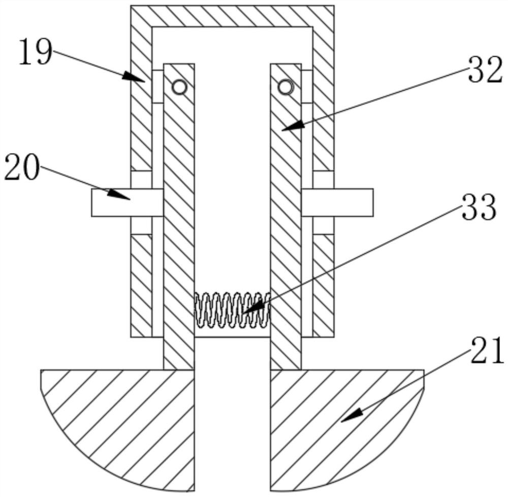
[0031] On the basis of Embodiment 1, the suspension assembly includes a suspension part 19, a suspension suction cup 34 is provided at the lower end of the suspension part 19 and a pressure regulating pump 35 is arranged therein, and the surface of the workpiece is attached to the suspension suction cup 34 Inhale air through the pressure regulating pump 35 to form a negative pressure in the suspension suction cup 34 to achieve the purpose of suspending the workpiece. After the spraying is completed, release the air through the pressure regulating pump 35 to cancel the negative pressure and remove the workpiece.

Embodiment 3

[0033] On the basis of Embodiment 1, one end of the drive assembly and the intermediate assembly is located inside the processing box 1, and the other end is located outside the side of the processing box 1, so that the distance between the processing box 1 and the outside can be reduced. Notches to reduce outward scattering of spray paint.


PUM


Abstract

The invention discloses a spraying device for electromechanical equipment part machining, and relates to the field of electromechanical equipment machining. The spraying device comprises a treatment box body, wherein a spraying assembly is arranged in the treatment box body. The spraying assembly comprises a plurality of spraying discs arranged on the inner side face and the upper and lower positions of the treatment box body correspondingly. A plurality of spraying heads are arranged on the spraying discs, a pigment box body is further arranged, a conveying hose used for connecting the pigment box body and the spraying discs is arranged between the pigment box body and the spraying discs, and a driving assembly, a middle assembly and a hanging assembly are further arranged. The spraying device is simple in structure and convenient to use. By arranging the hanging assembly, a workpiece can be conveniently hung and fixed for spraying, and by arranging the middle assembly, the workpiece can continuously rotate while moving, so that spraying is more uniform.

Description

technical field [0001] The invention relates to the technical field of electromechanical equipment processing, in particular to a spraying device for machining parts of electromechanical equipment. Background technique [0002] During the processing of parts of electromechanical equipment, many parts need to be sprayed and coated, but the existing spraying devices are fixed, and the nozzle part of some spraying devices can be moved to improve the uniformity of spraying, but The workpiece is still relatively fixed, which will lead to uneven thickness of the layer sprayed on it. Therefore, a spraying device for processing parts of electromechanical equipment is now provided. Contents of the invention [0003] The object of the present invention is to provide a spraying device for machining parts of electromechanical equipment, so as to solve the problems raised in the above-mentioned background technology. [0004] To achieve the above object, the present invention provides...

Claims


Application Information

Patent Timeline
IPC IPC(8): B05B13/02B05B16/00
CPCB05B13/0235B05B13/0264B05B16/00
Inventor 柳德清
Owner 佛山市顺德区豫锐涂装设备有限公司
Why Eureka
Try Eureka