A quick glue removal device for positioning holes of PCB boards for electrical engineering
A technology for PCB boards and electrical engineering, which is applied to the field of quick glue removal devices for positioning holes of PCB boards for electrical engineering, can solve the problems of inconvenient feeding and low efficiency of removing glue from PCB boards, and achieves convenient feeding and reduction of manual work. The number of feedings and the effect of convenient feeding
- Summary
- Abstract
- Description
- Claims
- Application Information
AI Technical Summary
Problems solved by technology
Method used
Image
Examples
Embodiment 1
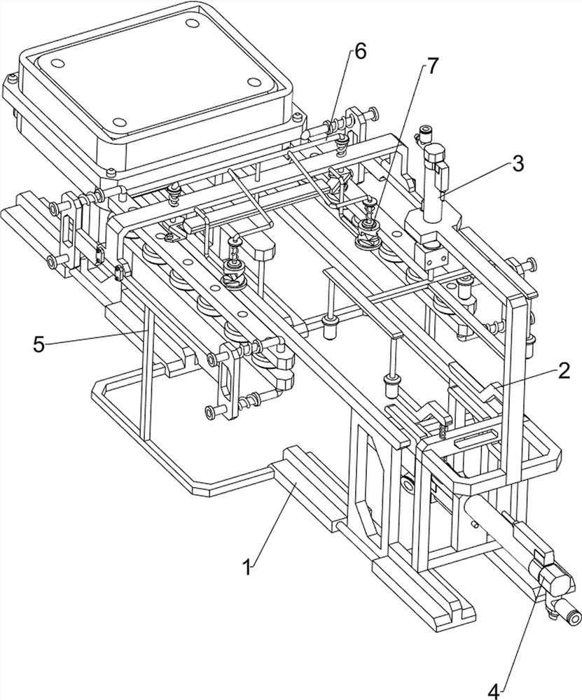
[0066] A kind of fast adhesive removal device for the positioning hole of the PCB board for electrical engineering, such as figure 1 As shown, it includes a base 1, a clamping mechanism 2 and a glue removing mechanism 3. The clamping mechanism 2 is arranged on the upper front of the base 1, and the glue removing mechanism 3 is arranged on the upper front side of the clamping mechanism 2.
[0067] When manually removing the glue in the positioning hole of the PCB board, the efficiency is low. The invention helps people improve the glue removal efficiency of the positioning hole of the PCB board. Firstly, the PCB board is placed in the clamping mechanism 2, and the clamping mechanism 2 clamps the PCB board Finally, start the glue removal mechanism 3, which will remove the glue on the positioning hole of the PCB board. After the glue removal is completed, close the glue removal mechanism 3 and take out the PCB board. When using the equipment again, repeat the above steps.
Embodiment 2
[0069] On the basis of Example 1, such as figure 2 and image 3As shown, the clamping mechanism 2 includes a first fixed frame 21, a first telescopic rod 22, a special-shaped clamp block 23 and a first spring 24, the upper front part of the base 1 is provided with a first fixed frame 21, and the first fixed frame 21 top Four first telescopic rods 22 are provided, and special-shaped clamping blocks 23 are arranged on the outside of the first telescopic rods 22, and first springs 24 are wound on the first telescopic rods 22, and the first springs 24 are connected with the first fixed frame 21 and the special-shaped clamping blocks. 23 connections.
[0070] When placing the PCB board, the PCB board is placed between the special-shaped clamping blocks 23 on the upper and lower sides, the PCB board squeezes the special-shaped clamping blocks 23 to move to the outside, the first spring 24 and the first telescopic rod 22 stretch, and the first spring 24 Give the special-shaped cla...
Embodiment 3
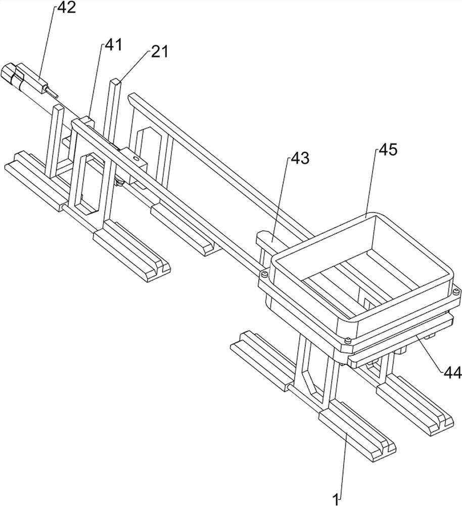
[0074] On the basis of Example 2, such as figure 1 , Figure 4 , Figure 5 , Figure 6 and Figure 7 As shown, it also includes a pusher mechanism 4, the base 1 is provided with a pusher mechanism 4, the pusher mechanism 4 is connected with the clamping mechanism 2, the pusher mechanism 4 includes a fixed seat 41, a second cylinder 42, a first fixed Plate 43, push block 44 and material discharge frame 45, first fixed frame 21 inner bottom side is provided with fixed seat 41, and second cylinder 42 is installed on the top of fixed seat 41, is provided with first fixed plate on the telescopic rod of second cylinder 42 43. A push block 44 is arranged on the upper side of the rear portion of the first fixed plate 43, and the push block 44 cooperates with the base 1, and a discharge frame 45 is arranged on the upper side of the rear portion of the base 1, and the discharge frame 45 cooperates with the push block 44.
[0075] People first place a large amount of PCB boards that ...
PUM
 Abstract
Description
Claims
Application Information
 - R&D
- Intellectual Property
- Life Sciences
- Materials
- Tech Scout
- Unparalleled Data Quality
- Higher Quality Content
- 60% Fewer Hallucinations
Browse by: Latest US Patents, China's latest patents, Technical Efficacy Thesaurus, Application Domain, Technology Topic, Popular Technical Reports.
© 2025 PatSnap. All rights reserved.Legal|Privacy policy|Modern Slavery Act Transparency Statement|Sitemap|About US| Contact US: help@patsnap.com


