A concrete aggregate pre-cooling device
A concrete aggregate and cooling device technology, which is applied in the direction of clay preparation device, mixing operation control device, pretreatment control, etc., can solve the problems of slow heat dissipation and low precooling efficiency, so as to increase the gap and improve the precooling efficiency Effect
- Summary
- Abstract
- Description
- Claims
- Application Information
AI Technical Summary
Problems solved by technology
Method used
Image
Examples
Embodiment 1
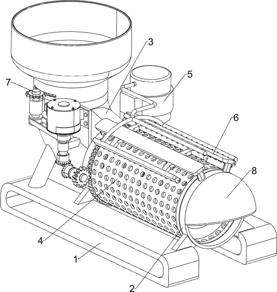
[0024] A concrete aggregate pre-cooling device, such as Figure 1-3 As shown, it includes a base 1, a mounting frame 2, a feeding pipe 3, a rotating mechanism 4, a pressurizing mechanism 5 and a water spray structure 6. The left and right sides of the top of the base 1 are connected with the mounting frame 2, and the left side of the top of the base 1 is connected. A feeding pipe 3 is connected, a rotating mechanism 4 is installed between the mounting frame 2 and the feeding pipe 3, a pressurizing mechanism 5 is installed on the top of the base 1, and the pressurizing mechanism 5 is connected with the rotating mechanism 4 by transmission, and the mounting frame 2 is installed with a The water spray structure 6 is connected with the pressurizing mechanism 5 .
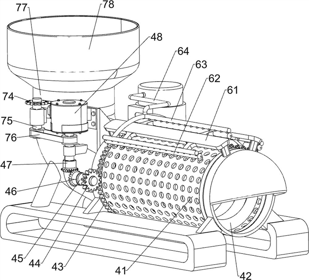
[0025] The rotating mechanism 4 includes a leaking drum 41, a screw pusher block 42, a first rack ring 43, a first gear 44, a fixed frame 45, a first bevel gear 46, a second bevel gear 47 and a servo motor 48, two of whi...
Embodiment 2
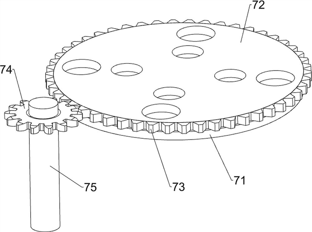
[0030] On the basis of Example 1, as Figure 1 to Figure 4As shown, it also includes a feeding amount control mechanism 7, and the feeding amount control mechanism 7 includes a fixed perforated plate 71, a rotary perforated plate 72, a second rack ring 73, a third gear 74, a transmission shaft 75, a first Two transmission belt groups 76, a casing 77 and a storage box 78, a transmission shaft 75 is rotatably connected to the upper part of the outer wall of the front side of the feeding pipe 3, a third gear 74 is connected to the transmission shaft 75, and the transmission shaft 75 is connected to the servo motor 48. A second transmission belt group 76 is connected between the output shafts, a casing 77 is connected to the top of the feed pipe 3, a fixed perforated plate 71 is connected inside the casing 77, and a rotary perforated plate 72 is rotatably connected to the top of the fixed perforated plate 71. A second rack ring 73 is connected to the outer wall of the rotary perfo...
PUM
 Abstract
Description
Claims
Application Information
 - R&D
- Intellectual Property
- Life Sciences
- Materials
- Tech Scout
- Unparalleled Data Quality
- Higher Quality Content
- 60% Fewer Hallucinations
Browse by: Latest US Patents, China's latest patents, Technical Efficacy Thesaurus, Application Domain, Technology Topic, Popular Technical Reports.
© 2025 PatSnap. All rights reserved.Legal|Privacy policy|Modern Slavery Act Transparency Statement|Sitemap|About US| Contact US: help@patsnap.com


