Wind turbine blade auxiliary manufacturing system and device
An auxiliary manufacturing system and wind turbine technology, applied in measuring devices, projection devices, optical devices, etc., can solve problems such as poor quality, lack of guidance for workers, and low manufacturing efficiency, and achieve accurate calibration and high projection accuracy.
- Summary
- Abstract
- Description
- Claims
- Application Information
AI Technical Summary
Problems solved by technology
Method used
Image

Examples
Embodiment 2
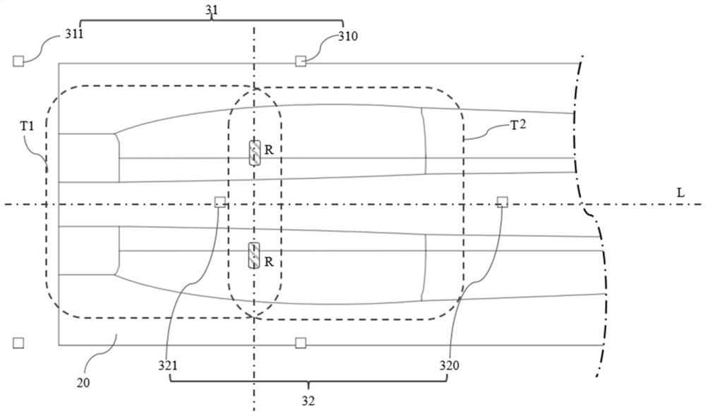
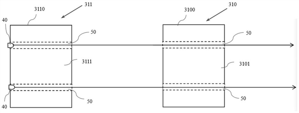
[0045] In this embodiment, the first auxiliary system 31 includes two first laser projection devices 310 respectively located on both sides above the blade mold 20, and two first optical imaging devices 311 respectively located on both sides above the blade mold 20. A laser projection device 310 and the first optical imaging device 311 are located at different positions along the longitudinal axis L of the blade mold 20 . In practice, in order to accurately shoot laser projection images and the blade manufacturing process, the camera device needs to use a telephoto lens. Due to the limited field of view, and considering the small area near the end surface of the root of the blade, the root can be arranged in the camera The proximal section of the area, the middle or tip of the blade is arranged at the far end of the imaging area. To sum up, in this embodiment, preferably, the first optical imaging device 311 is located closer to the mold root 22 of the blade mold 20 , and the ...
Embodiment 3
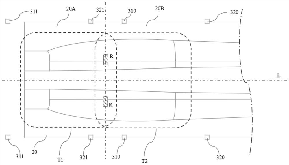
[0049] In this example, if Figure 4 and Figure 5 As shown, the blade mold 20 is divided into adjacent first section 20A and second section 20B, wherein the first section includes the mold root 22 of the aforementioned blade mold 20, and the aforementioned first auxiliary system 30 is used for the second A section 20A is projected and imaged. In addition, the blade manufacturing auxiliary system 30 also includes a second auxiliary system 32. The second auxiliary system 32 projects and images the second section 20B and includes at least one second laser projection device 320 and At least one second optical imaging device 321 and a second laser projection device 320 are installed above the blade mold 20 for projecting second operation guide graphics and structured light for assisting three-dimensional measurement on the blade. The second optical imaging device 321 is installed above the blade mold 20 to obtain the second operation guide pattern projected on the blade, the stru...
Embodiment 4
[0055] In this implementation, the blade manufacturing auxiliary system 30 also includes a control device (not shown), which is connected in communication with the first laser projection device 310 and the first optical imaging device 311 to read the blade drawing information , and obtain the three-dimensional model of the blade and / or the blade mold 20 in the blade manufacturing process through the imaging information collected from the first optical imaging device, and based on the blade drawing information and the three-dimensional model, control the first laser projection device 310 to project the required The first operation guide graphic. Wherein, the imaging information includes imaging of structured light for assisting three-dimensional measurement and imaging of leaves under ambient light. Further, the imaging information may also include a first operation guide graphic, and the position of the first operation guide graphic is adjusted based on an error of the project...
PUM
 Abstract
Description
Claims
Application Information
 - R&D
- Intellectual Property
- Life Sciences
- Materials
- Tech Scout
- Unparalleled Data Quality
- Higher Quality Content
- 60% Fewer Hallucinations
Browse by: Latest US Patents, China's latest patents, Technical Efficacy Thesaurus, Application Domain, Technology Topic, Popular Technical Reports.
© 2025 PatSnap. All rights reserved.Legal|Privacy policy|Modern Slavery Act Transparency Statement|Sitemap|About US| Contact US: help@patsnap.com