Fixing support of automobile driving shaft

A technology for fixing brackets and drive shafts, applied in the field of vehicles, can solve problems such as frequent failures of drive shaft brackets, and achieve the effects of frequent failures, low vibration, and low noise

Active Publication Date: 2021-04-09
CHERY AUTOMOBILE CO LTD
View PDF8 Cites 0 Cited by
  • Summary
  • Abstract
  • Description
  • Claims
  • Application Information

AI Technical Summary

Problems solved by technology

[0005] An embodiment of the present disclosure provides a fixed bracket for an automobile drive shaft, which can solve the problem of frequent failures at the drive shaft bracket

Method used


Image

  • Fixing support of automobile driving shaft
  • Fixing support of automobile driving shaft
  • Fixing support of automobile driving shaft

Examples


Embodiment Construction

[0041] In order to make the purpose, technical solution and advantages of the present disclosure clearer, the implementation manners of the present disclosure will be further described in detail below in conjunction with the accompanying drawings.

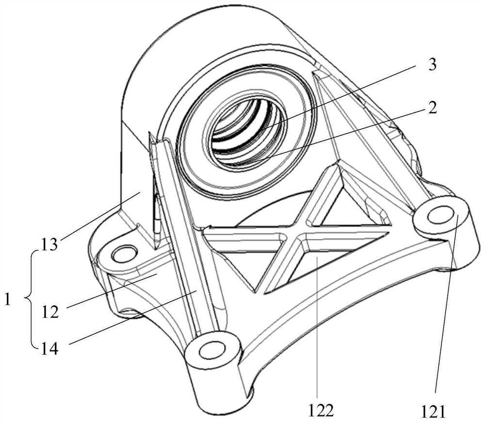
[0042] An embodiment of the present disclosure provides a fixed bracket for an automobile drive shaft, such as figure 1 As shown, the fixed bracket includes a support 1 , a stator ring assembly 2 and a rotor ring assembly 3 .

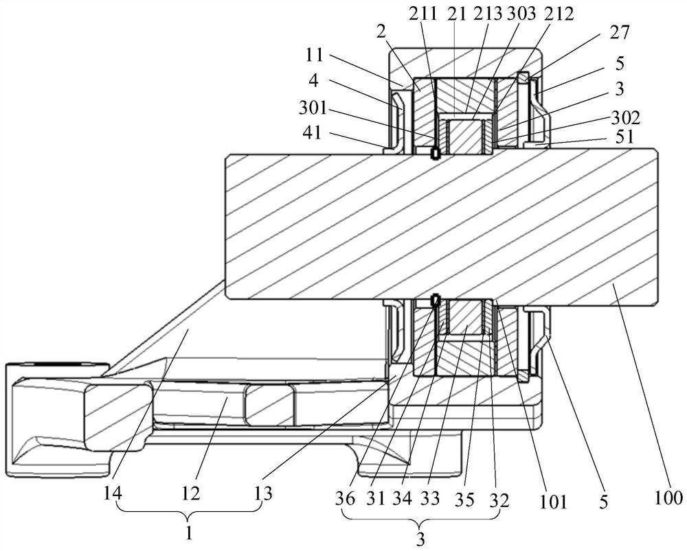
[0043] figure 2 It is a cross-sectional view of a fixed bracket of an automobile drive shaft provided by an embodiment of the present disclosure, combined with figure 2, the stator ring assembly 2 is connected to the support 1, the inner peripheral wall of the stator ring assembly 2 has an annular groove 21, the annular groove 21 is coaxial with the stator ring assembly 2, and the annular groove 21 includes a first inner groove wall 211, a second inner groove wall 212 and the inner groove bottom 213, the...


PUM


Abstract

The invention provides a fixing support of an automobile driving shaft, and belongs to the technical field of vehicles. The fixing support comprises a support, a stator ring assembly and a rotor ring assembly. The stator ring assembly is connected with the support, an annular groove is formed in the inner circumferential wall of the stator ring assembly and comprises a first inner groove wall, a second inner groove wall and an inner groove bottom, the rotor ring assembly comprises a first outer side wall, a second outer side wall and an outer circumferential wall, the first outer side wall and the first inner groove wall are identical in magnetism, and the second outer side wall and the second inner groove wall are identical in magnetism. The magnetism of the outer peripheral wall is the same as that of the inner groove bottom, the rotor ring assembly is rotatably and coaxially inserted into the annular groove, the first outer side wall is opposite to and spaced from the first inner groove wall of the annular groove, the second outer side wall is opposite to and spaced from the second inner side wall of the annular groove, and the outer peripheral wall is opposite to and spaced from the inner groove bottom. The problem that faults frequently occur at the driving shaft support can be solved through the fixing support.

Description

technical field [0001] The disclosure belongs to the technical field of vehicles, and in particular relates to a fixing bracket of an automobile drive shaft. Background technique [0002] The car drive shaft assembly mainly has two-stage and three-stage types. Due to the limitation of the installation space of the drive shaft, and to avoid torque steering and excessive length of the shaft, the car drive shaft assembly is generally designed as a three-stage type. [0003] In the related art, the three-section automobile drive shaft includes a left shaft, an intermediate shaft and a right shaft, and the intermediate shaft needs to be installed on the engine through the drive shaft bracket. The drive shaft bracket is generally composed of a support, a ball bearing, and the like. Wherein, the intermediate shaft is assembled on the ball bearing, and the ball bearing is assembled in the support, and the support is fixedly connected with the engine block. [0004] However, when t...

Claims


Application Information

Patent Timeline
Patent Type & Authority Applications(China)
IPC IPC(8): B60K17/24H02N15/00
CPCB60K17/24H02N15/00
Inventor 毛松磊王道玉孙利飞石建伟钱建功童家金范文来
Owner CHERY AUTOMOBILE CO LTD
Why Eureka
Try Eureka