Auxiliary power system control method based on finite-state machine and electronic controller

A finite state machine and auxiliary power technology, which is applied to auxiliary power equipment, aircraft parts, transportation and packaging, etc., can solve the problems of increasing the difficulty of locating faults, the inability of data to support troubleshooting content, complex control logic, etc.

Active Publication Date: 2021-04-09
XIAN AVIATION COMPUTING TECH RES INST OF AVIATION IND CORP OF CHINA
View PDF8 Cites 0 Cited by
  • Summary
  • Abstract
  • Description
  • Claims
  • Application Information

AI Technical Summary

Problems solved by technology

[0003] As the types of energy / functions provided by the auxiliary power system for the aircraft become more and more abundant, there are more and more components, and the control logic becomes more and more complex. The higher the increase, the existing data cannot support the troubleshooting content after a fault occurs in the control process, which increases the difficulty of locating the fault

Method used


Image

  • Auxiliary power system control method based on finite-state machine and electronic controller
  • Auxiliary power system control method based on finite-state machine and electronic controller
  • Auxiliary power system control method based on finite-state machine and electronic controller

Examples


Embodiment Construction

[0172] The present invention will be further described below in conjunction with the accompanying drawings and specific embodiments.

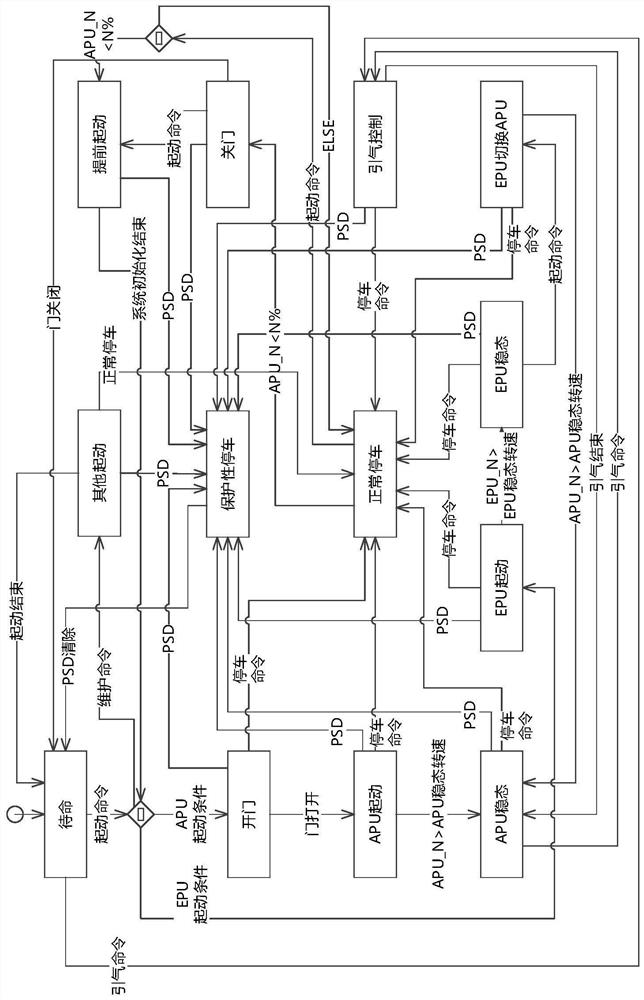
[0173] Such as figure 1 As shown, the working states of the auxiliary power system in the control strategy based on the finite state machine in this embodiment include: standby state, door open state, APU start-up dynamic, APU steady state, EPU start-up dynamic, EPU steady state, EPU switching APU state, boot state Gas control state, normal parking state, protective parking state, door closing state, other starting states and early starting states.

[0174] The following steps are used to complete the entire control process:

[0175] 1. When the auxiliary power system is in the standby state, the relevant operations of power-on self-inspection and system initialization should be completed;

[0176] 1.1. When the start command is received, the entry state should be judged according to the specific working conditions at the start time;

[0177...


PUM


Abstract

The invention belongs to the field of aviation power control, and relates to an auxiliary power system control method based on a finite-state machine and an electronic controller. System control can be carried out through a finite-state machine according to different starting modes of the auxiliary power system. On the basis of a traditional control strategy, the control method based on the finite-state machine is designed, a system with discrete characteristics can be reproduced through a series of control strategies for describing a controlled object in a finite state, modeling is conducted on external behavior characteristics of the controlled object, and therefore the control precision of the controlled object is improved. According to the method, the development and change rules of the whole system can be accurately mastered, meanwhile, the internal logic of the target system is visually described in the graphical form, and effective troubleshooting after the system breaks down is also facilitated.

Description

technical field [0001] The invention belongs to the field of aviation power control, and relates to a method for controlling an auxiliary power system. The system can be controlled by means of a finite state machine according to different starting modes of the auxiliary power system. Background technique [0002] The auxiliary power system is a power system independent of the engine, which is used to provide auxiliary or emergency energy, bleed air power, hydraulic power and electric power to the aircraft, and is a key system to ensure the safe flight of the aircraft. [0003] As the types of energy / functions provided by the auxiliary power system for the aircraft become more and more abundant, there are more and more components, and the control logic becomes more and more complex. The higher the value, the more difficult it is to locate the fault after the fault occurs in the control process, and the existing data cannot support the troubleshooting content. Contents of t...

Claims


Application Information

Patent Timeline
Patent Type & Authority Applications(China)
IPC IPC(8): B64D41/00
CPCB64D41/00
Inventor 唐甜王瑞吕伟谭琪璘高博马振华
Owner XIAN AVIATION COMPUTING TECH RES INST OF AVIATION IND CORP OF CHINA
Why Eureka
Try Eureka