Working method of disc workpiece ball placing mechanism

A working method and ball technology, which is applied to the ball placement mechanism of disc workpieces and the field of transmission and processing of disc workpieces, can solve the problem of affecting the efficiency and quality of ball placement, reduce the production and processing speed of disc workpieces, and accurately adjust to the required position And other issues

Inactive Publication Date: 2021-04-09
葛巧红
View PDF2 Cites 6 Cited by
  • Summary
  • Abstract
  • Description
  • Claims
  • Application Information

AI Technical Summary

Problems solved by technology

Disc workpieces are commonly used workpieces now. During the production and processing of disc workpieces, the disc workpieces need to undergo processing steps such as die-casting, grinding and drilling in sequence. After the above processing steps, according to the subsequent use of the disc workpiece According to the needs of the disc workpiece, it is necessary to evenly place multiple balls on the outside of the disc workpiece, so that the disc workpiece can realize the role of supporting and rotating during specific use. Placement one by one, the work intensity of the workers is high and the work efficiency is low. The existing ball placement is also commonly used to grab and place the balls with a manipulator. Continuous and accurate placement, the existing disc workpiece cannot be adjusted to the desired position smoothly and conveniently before the ball is placed, and the existing disc workpiece is difficult to adjust according to the ball during the ball placement process. The placement needs to be adjusted horizontally and smoothly, which leads to the inability to place the balls uniformly on the outer side of the disc workpiece, which affects the efficiency and quality of ball placement, reduces the production and processing speed of the disc workpiece, and cannot meet the needs of processing and use.

Method used


Image

  • Working method of disc workpiece ball placing mechanism
  • Working method of disc workpiece ball placing mechanism
  • Working method of disc workpiece ball placing mechanism

Examples


Embodiment Construction

[0015] In order to further describe the present invention, the specific implementation of a disc workpiece ball placement mechanism will be further described below in conjunction with the accompanying drawings. The following examples are explanations of the present invention and the present invention is not limited to the following examples.

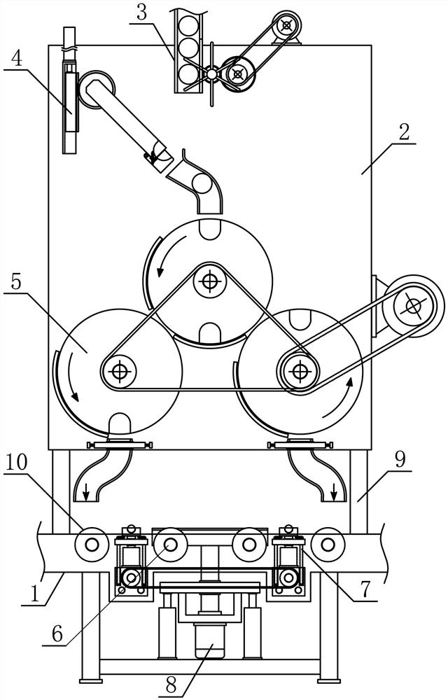
[0016] Such as figure 1 As shown, a disc workpiece ball placement mechanism of the present invention includes a disc support 1, a bead support 2, a bead drop mechanism 3, a bead guide mechanism 4, a branching mechanism 5, a bearing plate guide roller 6, and a limit mechanism 7 And the supporting plate mechanism 8, the bead passing support 2 is vertically fixedly arranged on one side above the passing plate support 1, and the fixed supporting rods 9 are vertically fixed respectively between the two sides below the bead passing support 2 and the passing plate support 1, and the bead passing The middle part of the upper side of the bracket ...


PUM


Abstract

The invention discloses a working method of a disc workpiece ball placing mechanism, and belongs to the field of mechanical equipment for workpiece machining. A ball conveying support is vertically and fixedly arranged on one side of the upper portion of a disc conveying support, a ball guiding mechanism is fixedly arranged on the disc conveying support on one side of a ball falling mechanism, a branching mechanism is vertically and fixedly arranged on one side of the lower portion of the ball conveying support, and a plurality of disc conveying rotating rollers are sequentially and horizontally connected with the disc conveying support in a rotating mode in the horizontal direction. Limiting mechanisms are horizontally and symmetrically arranged on the portions, on the two sides below the branching mechanism, of the disc conveying support respectively, a disc bearing mechanism is vertically arranged on the disc conveying support in the middle of the lower side of the branching mechanism, a transferring disc is vertically and rotationally connected th the ball conveying support on the lower side of a ball guiding pipe, and a first branching rotary disc and a second branching rotary disc are symmetrically arranged on the two sides below the transferring disc. The disc workpiece ball placing mechanism is reasonable in structural design and capable of meeting the requirement for continuous and accurate placement of disc workpiece balls of various sizes and specifications, the automation degree of workpiece production and machining is improved, and the machining and using requirements are met.

Description

technical field [0001] The invention belongs to the field of workpiece processing machinery and equipment, and in particular relates to a working method of a disc workpiece ball placement mechanism, which is mainly applied to the transmission and processing of disc workpieces. Background technique [0002] The mechanical workpiece is a single piece that makes up the machine and its inseparability. It plays an important role in the automation industry. The mechanical workpiece includes the connection of parts, the supporting parts, the lubricating lubrication system and the sealing Components, components of the transmission system that transmits motion and energy, there are many types of workpieces, which can be mainly divided into: shaft sleeve workpieces, disc cover workpieces, fork bracket workpieces and box body workpieces according to the function and shape of the workpiece. The main part of the shaft sleeve workpiece is a coaxial revolving body, which mainly plays the r...

Claims


Application Information

Patent Timeline
Patent Type & Authority Applications(China)
IPC IPC(8): B65G47/80B65G47/29B65G47/88B65G47/52B65G47/82B65G47/74
CPCB23P19/001
Inventor 葛巧红
Owner 葛巧红
Why Eureka
Try Eureka