
Fan blade and aero-engine

A technology of fan blades and hollowing out, which is applied in the directions of machines/engines, liquid fuel engines, mechanical equipment, etc. It can solve problems such as the inability to form a suspended structure, the inability to form an entire sphere from a suspended point, and the infeasibility of the principle.

Active Publication Date: 2021-04-09
AECC COMML AIRCRAFT ENGINE CO LTD
View PDF7 Cites 0 Cited by
  • Summary
  • Abstract
  • Description
  • Claims
  • Application Information

AI Technical Summary

Problems solved by technology

The invention mentions the use of 3D printing technology to manufacture hollow blades to obtain more complex blade structures, but it is difficult to achieve in practice, because although 3D printing can manufacture complex three-dimensional structures, it cannot form suspended structures, nor That is to say, the spherical network structure cannot form an entire sphere from a suspended point, and then cross-link with other spheres. Therefore, although this patent provides the idea of ​​using 3D printing in blade manufacturing, it is actually not feasible in principle.

Method used


Image

  • Fan blade and aero-engine
  • Fan blade and aero-engine
  • Fan blade and aero-engine

Examples


Embodiment Construction

[0035] The content of the present disclosure and the points of difference between the present disclosure and the prior art can be understood below with reference to the drawings and text. The technical solutions (including preferred technical solutions) of the present disclosure will be further described in detail below by means of the accompanying drawings and listing some optional embodiments of the present disclosure.

[0036] It should be noted that: any technical feature and any technical solution in this embodiment are one or more of a variety of optional technical features or optional technical solutions. Citing all the alternative technical features and alternative technical solutions of the present disclosure, it is not convenient for the implementation of each technical feature to emphasize that it is one of the optional multiple implementation modes, so those skilled in the art should know that: A new technical solution is obtained by replacing any technical means p...


PUM


Abstract

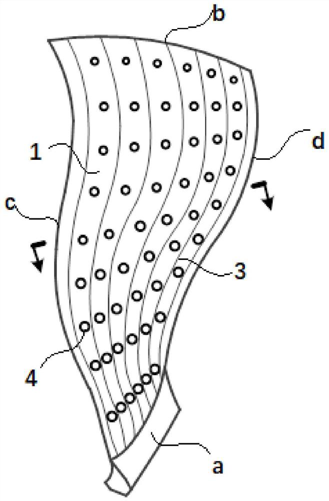
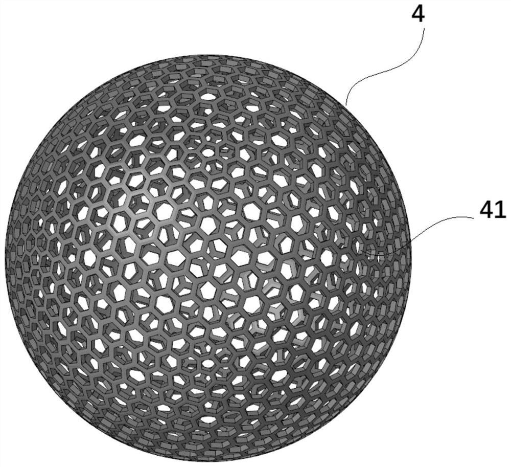
The invention discloses a fan blade. The fan blade comprises a first face plate, a second face plate, a plurality of partition plates and a plurality of fillers, wherein the first face plate is arranged on the windward side; the second face plate corresponds to the first face plate and is arranged on the leeward side; the partition plates are supported between the first face plate and the second face plate at intervals and can divide the interior of the fan blade into a plurality of cavities; and the plurality of fillers fill the cavity and are fixed relative to the positions of the first face plate and the second face plate. Based on the technical scheme, the fillers can be used for absorbing the bird impact load of the fan blade, so that the bird impact resistance of the fan blade can be improved; the fan blade has higher hollow ratio and smaller weight under the conditions of equivalent strength, rigidity and bird impact resistance; and meanwhile, the processing and manufacturing efficiency of the fan blade is high, and the quality is stable.

Description

technical field [0001] The present disclosure relates to the field of gas turbines, in particular to a fan blade and an aeroengine. Background technique [0002] High bypass ratio fan blades are key components of large airliner engines. Traditional solid fan blades have heavy weight, high centrifugal force, prominent flutter and vibration problems, and can no longer meet the requirements of passenger engine design and low fuel consumption. Superplastic forming / diffusion connection Valen structure titanium alloy wide-chord hollow fan blades and carbon fiber Composite material fan blades are a typical structure of the current international high bypass ratio turbofan engine, but they are all protected by the patents of foreign aero-engine manufacturers. [0003] At the same time, a large number of patents have proposed 3D printing technology related to aero-engines. According to the public patent search, 3D printing technology has been widely used in many parts of the engine, ...

Claims


Application Information

Patent Timeline
Patent Type & Authority Applications(China)
IPC IPC(8): F04D29/26
CPCF04D29/26F05D2240/30F05D2240/301F05D2220/36
Inventor 冯锦璋柴象海
Owner AECC COMML AIRCRAFT ENGINE CO LTD
Learn More