Tension peeling testing machine

A testing machine and tension technology, which is applied in the direction of applying stable tension/pressure to test the strength of materials, measuring devices, instruments, etc. It can solve the problems that the rope cannot be in a horizontal state and cannot move height

Inactive Publication Date: 2021-04-09
SHENGZHOU YIYUAN INVESTMENT MANAGEMENT
View PDF0 Cites 3 Cited by
  • Summary
  • Abstract
  • Description
  • Claims
  • Application Information

AI Technical Summary

Problems solved by technology

[0009] The purpose of the present invention is to provide a tensile peeling tester to solve the problem that the height cannot be moved during the detection in the above background technology, resulting in the problem that the rope cannot be in a horizontal state during the detection

Method used


Image

  • Tension peeling testing machine
  • Tension peeling testing machine
  • Tension peeling testing machine

Examples


Embodiment 1

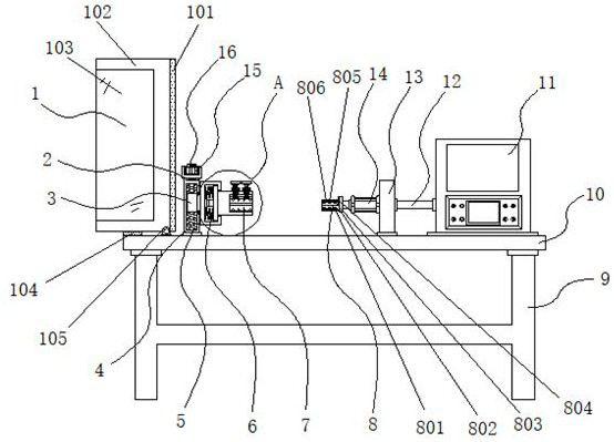
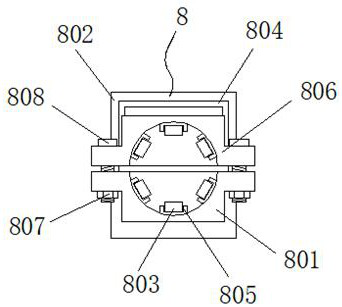
[0035] Example 1: See Figure 1-6 , a tensile peel testing machine, comprising a tensile peel testing machine, including a bracket 9 and a workbench 10, the top of the bracket 9 is fixedly connected with a workbench 10, and the top of the workbench 10 is fixedly connected with a mounting column 13, and the workbench 10 One side of the top is fixedly connected with a controller 11, and one side of the installation column 13 is fixedly connected with a hydraulic cylinder 14, the type of the hydraulic cylinder 14 is HOB, and the output end of the hydraulic cylinder 14 is provided with an anti-off structure 8, and the hydraulic cylinder 14 One side is fixedly connected with a connection line 12, the connection line 12 runs through the mounting column 13 and is fixedly connected with the controller 11, a protective structure 1 is provided on one side of the top of the workbench 10, and a trigger mechanism 6 is provided on the top of the workbench 10, and the trigger mechanism 6 One...

Embodiment 2

[0039] Embodiment 2: Protective structure 1 is made up of rubber strip 101, protective cover 102, window 103, placement pad 104 and hinge block 105, and hinge block 105 is fixedly connected to the two ends of workbench 10 top side, and one end of hinge block 105 is movable Connected with a protective cover 102, one side of the protective cover 102 is fixedly connected with a rubber strip 101, the inside of the protective cover 102 is fixedly connected with a window 103, and the placement pad 104 is fixedly connected to the top side of the workbench 10, and the placement pad 104 and the protective cover 102 active connections;

[0040] The center line of window 103 and the center line of protective cover 102 are on the same horizontal plane, and the height of rubber strip 101 is equal to the height of protective cover 102;

[0041] Specifically, as figure 1 and Image 6 As shown, after the rope is fixed, turn over the protective cover 102 to attach the rubber strip 101 to the...

Embodiment 3

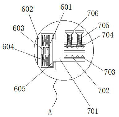
[0042] Embodiment 3: The trigger mechanism 6 is composed of a bump 601, a movable groove 602, a trigger 603, a spring 604 and a limit plate 605. The movable groove 602 is fixedly connected to one side of the threaded sleeve 3, and the inner side of the movable groove 602 A group of springs 604 are fixedly connected to both ends respectively, one side of the spring 604 is fixedly connected to the limiting plate 605, one side of the limiting plate 605 is fixedly connected to a bump 601, and one side inside the movable groove 602 is fixedly connected to a trigger 603;

[0043] The centerline of the bump 601 and the centerline of the trigger 603 are on the same horizontal plane;

[0044] Specifically, as figure 1 , image 3 and Figure 5 As shown, when using this device to detect, one side of the rope is fixed inside the fixed structure 7, and the hydraulic cylinder 14 is activated to pull the rope to the other side through the anti-off structure 8. When the rope breaks, the fix...


PUM


Abstract

The invention discloses a tension peeling testing machine, and particularly relates to the technical field of tension testing, the tension peeling testing machine comprises a support and a workbench, the top end of the support is fixedly connected with the workbench, the top end of the workbench is fixedly connected with a mounting column, and one side of the top end of the workbench is fixedly connected with a controller; and a hydraulic oil cylinder is fixedly connected to one side of the mounting column, and an anti-falling structure is arranged at the output end of the hydraulic oil cylinder. By arranging the tooth grooves, the threaded sleeves, the screw rods, the stand columns, the limiting gears and the lifting handles, when the device is used for testing a rope, after the rope is fixed, the lifting handles are lifted to pull the limiting gears out of the tooth grooves, the limiting gears are rotated to drive the hydraulic oil cylinders to rotate, and the hydraulic oil cylinders rotate to drive the external threaded sleeves to ascend and descend; and when the two sides of the rope are flush with each other, the lifting handle is inserted into the tooth groove to be fixed, and the rope can be kept horizontal in the testing process.

Description

technical field [0001] The invention relates to the technical field of tensile testing, in particular to a tensile peeling testing machine. Background technique [0002] Ropes are very common in our lives. They can easily connect multiple objects together. They are often used in transportation, transportation, construction and other industries. Ropes have different pull-resistant capabilities depending on their materials and diameters. They all have The limit value of a tensile force is the limit value of its tensile force at the moment of its breakage, that is, the moment of tensile peeling. In order to test this value, there are some testing machines for tensile peeling, but there are always some defects in the detection. , resulting in inaccurate test values, a more practical tensile peel tester is now needed. [0003] In the process of realizing the present invention, the inventors have found that at least the following problems in the prior art have not been resolved: ...

Claims


Application Information

Patent Timeline
Patent Type & Authority Applications(China)
IPC IPC(8): G01N3/02G01N3/04G01N3/10
CPCG01N3/02G01N3/04G01N3/10
Inventor 杨仲英梁梅芹
Owner SHENGZHOU YIYUAN INVESTMENT MANAGEMENT
Why Eureka
Try Eureka