Vehicle tail gas puff positioning detection method, device, and equipment, storage medium and system

A positioning detection, vehicle technology, applied in the computer field, can solve problems such as inability to detect exhaust gas

Active Publication Date: 2021-04-09
安徽宝龙环保科技有限公司
View PDF7 Cites 0 Cited by
  • Summary
  • Abstract
  • Description
  • Claims
  • Application Information

AI Technical Summary

Problems solved by technology

[0005] The purpose of the embodiments of the present invention is to provide a method, device, equipment, storage medium and system for positioning and detecting vehicle exhaust puffs, aiming to solve the problem that the existing vertical exhaust remote measurement equipment cannot realize the positioning of vehicle exhaust puffs , so that it is impossible to perform exhaust gas detection on vehicles whose exhaust pipes are not at the rear of the vehicle

Method used


Image

  • Vehicle tail gas puff positioning detection method, device, and equipment, storage medium and system
  • Vehicle tail gas puff positioning detection method, device, and equipment, storage medium and system
  • Vehicle tail gas puff positioning detection method, device, and equipment, storage medium and system

Examples


Embodiment Construction

[0038] In order to make the object, technical solution and advantages of the present invention clearer, the present invention will be further described in detail below in conjunction with the accompanying drawings and embodiments. It should be understood that the specific embodiments described here are only used to explain the present invention, not to limit the present invention.

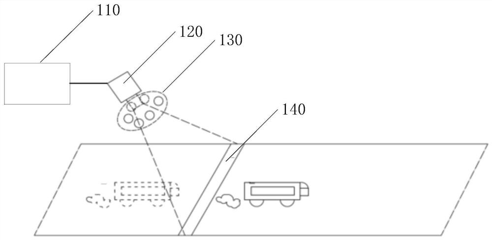
[0039] Such as figure 1 As shown, it is an application environment diagram of a vehicle exhaust puff location detection method provided by an embodiment of the present invention, which can also be understood as a structural schematic diagram of a vehicle exhaust puff location detection system, which is described in detail as follows.

[0040] In the embodiment of the present invention, the vehicle exhaust puff location detection system specifically includes a vehicle exhaust puff location detection device 110 , an infrared array signal transceiver device 120 , a chopper disc 130 and a reflective ta...


PUM


Abstract

The invention is applicable to the technical field of computers, and particularly relates to a vehicle tail gas puff positioning detection method, device and equipment, a storage medium and a system. The method comprises the following steps: obtaining multiple frames of reflective band spectral images, collected under a periodically-changed infrared band, of a vehicle when the vehicle passes through a reflective band and splicing according to the time sequence; determining a reflective tape CO2 absorbance image and a reference matrix under different infrared bands, and correcting the reflective tape CO2 absorbance image by using the reference matrix; and determining the position information of the vehicle tail gas puff, and further detecting the vehicle tail gas puff according to the position information. According to the vehicle tail gas puff positioning detection method, the CO2 waveband spectrum diagram is used for positioning the position of the tail gas puff, the reference waveband spectrum is used for eliminating the influence of factors such as light intensity, and the defect that an existing vertical tail gas tele-metering device cannot position the vehicle tail gas puff can be well overcome; tail gas detection of a vehicle with an exhaust pipe not located at the tail of the vehicle can be achieved.

Description

technical field [0001] The invention belongs to the technical field of computers, and in particular relates to a vehicle exhaust puff location detection method, device, equipment, storage medium and system. Background technique [0002] The analysis of the components in the vehicle exhaust puff can effectively prevent the emission of highly polluting exhaust and protect the environment. In the prior art, most of the analysis of the components in the vehicle exhaust puff is based on the vertical exhaust telemetry equipment. Specifically, when the front of the vehicle reaches the reflection zone, the reflected signal of the test host is blocked, while in the vehicle The moment the tail leaves the reflection band, the test host can receive the reflected spectrum signal again, so that it can immediately start to collect the spectrum continuously, and analyze and calculate the CO in the tail gas. 2 , CO, C 3 h 8 , the concentration of NO and other gases with different componen...

Claims


Application Information

Patent Timeline
IPC IPC(8): G06T7/70G06T7/90G06T7/13
CPCG06T7/70G06T7/90G06T7/13G06T2207/10048
Inventor 吴丽明刘进蒋晓川马磊吴菲方传胜宣光银张晶晶
Owner 安徽宝龙环保科技有限公司
Why Eureka
Try Eureka