
Camera

An imaging device, solid-state imaging technology, applied in image communication, signal generator with a single pickup device, television, etc., can solve the problems of difficult signal processing, reduced transmission efficiency, deterioration, etc.

Inactive Publication Date: 2003-10-29
VICTOR CO OF JAPAN LTD
View PDF0 Cites 0 Cited by
  • Summary
  • Abstract
  • Description
  • Claims
  • Application Information

AI Technical Summary

Problems solved by technology

As a result, the problem is that the transmission efficiency is reduced, and the CDS and ADC are difficult to deal with the signal processing deterioration caused by the high frequency. In order to avoid this situation, another device must be installed.

Method used


Image

  • Camera
  • Camera
  • Camera

Examples


Embodiment Construction

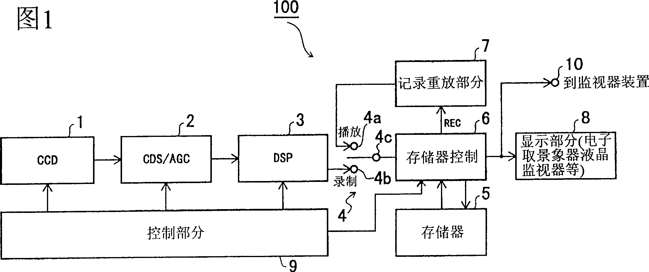
[0025] As shown in FIG. 1 , a camera device 100 as an embodiment of the present invention has: a CCD image sensor 1, which photographs an object; a correlated double sampling / automatic gain control section 2 (CDS / AGC), which adopts Remove the noise component from the camera signal output by the CCD image sensor 1, and at the same time amplify and output the signal with an appropriate gain; the digital signal processor 3 (DSP) performs specified video processing on the camera signal output by the CDS / AGC2 and then outputs it.

[0026] In addition, the video camera device 100 shown in Fig. 1 also has: memory 5, is used for temporarily storing the imaging signal output from DSP 3; Change-over switch 4 selects the camera signal output by the above-mentioned DSP 3 when recording, and selects the camera signal played back by the above-mentioned recording and playback part 7 when reproducing; the storage control part 6 controls the access of the memory 5 .

[0027] In addition, this...


PUM


Abstract

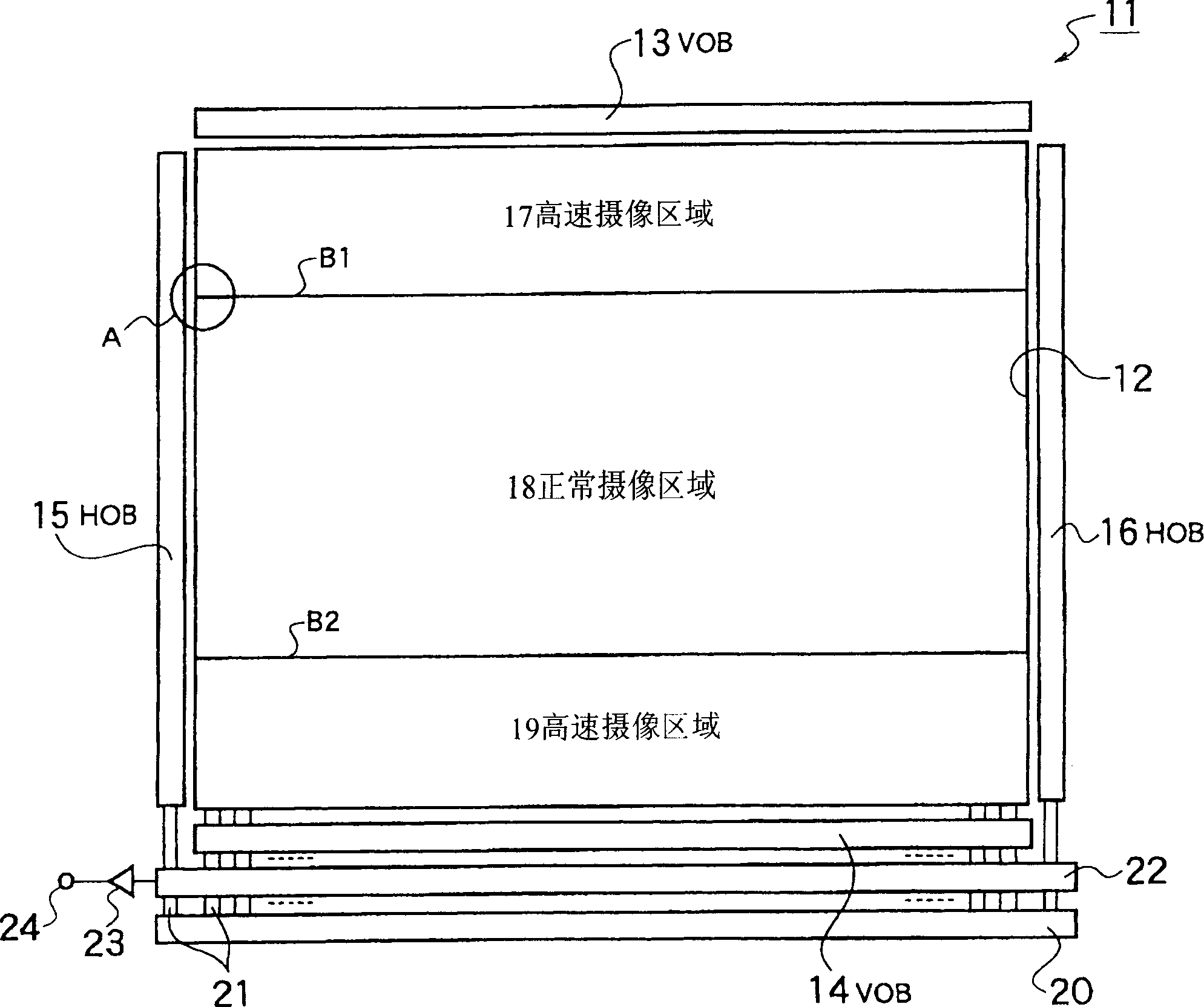
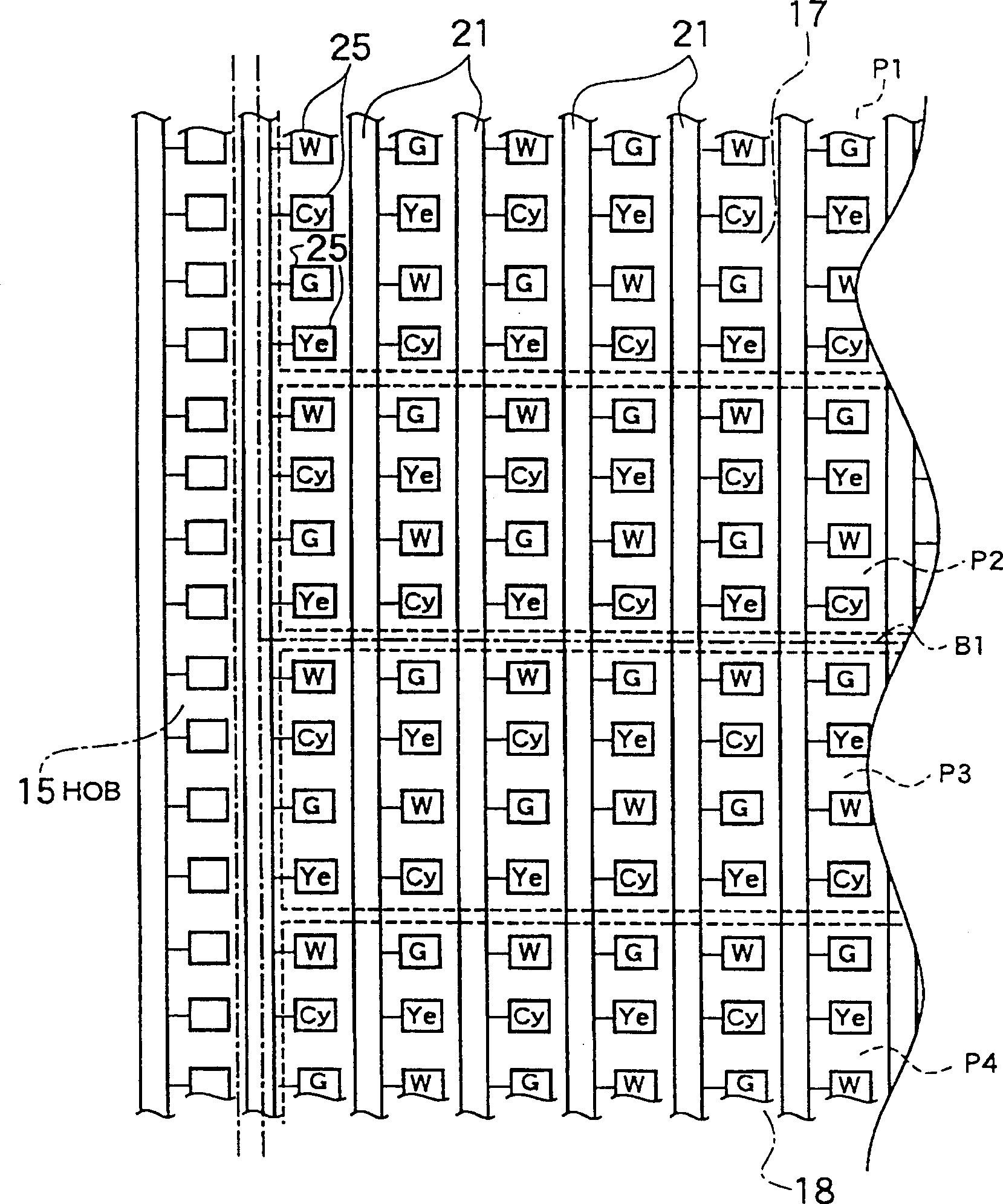
High-speed imaging can be realized without making significant changes to existing imaging devices such as CCDs. The imaging device 100 has a solid-state imaging unit 11 in which various photoelectric conversion elements 25 that detect different colors of light are arranged in a polylattice shape, and the charge accumulated by these photoelectric conversion elements is read out as an electrical signal for imaging. Each photoelectric conversion element 25 is read out multiple times in one field period, and at the same time, the discharge device 20 clears the electric charge accumulated in the photoelectric conversion element 25 . . .

Description

technical field [0001] The present invention relates to imaging devices such as a CCD, a camera device, and a camera device that use a solid-state imaging device to image a subject. Background technique [0002] In conventional imaging devices, a solid-state imaging unit (CCD image sensor) formed of a solid-state imaging element is incorporated in the imaging device in order to realize smaller size, lighter weight and lower cost than the imaging tube. Fig. 5 shows the general structure of this CCD image sensor. [0003] In this figure, a CCD image sensor 50 has: a photoelectric conversion element 51 arranged in a vertical direction to sense light of different colors and convert it into charge accumulation; a vertical transfer path 52 makes these photoelectric conversion elements 51 accumulate The charges transferred in the vertical direction; the horizontal transfer path 53 transfers the charges transferred in the vertical transfer path 52 in the horizontal direction. [0...

Claims


Application Information

Patent Timeline
IPC IPC(8): H04N5/335H04N5/341H04N5/345H04N5/353H04N5/357H04N5/359H04N5/363H04N5/369H04N5/372H04N5/378H04N9/07
CPCH04N25/443H04N25/73
Inventor 宫原弘之
Owner VICTOR CO OF JAPAN LTD
Learn More