Surfacial assembler

A technology of surface mounting machine and camera device, which is applied to conveyor objects, transportation and packaging, electrical components, etc., can solve the problems of poor installation performance, longer moving distance, and damaged suction nozzles, so as to avoid mutual interference. , The effect of suppressing damage to the nozzle and shortening the moving distance

Active Publication Date: 2006-02-01
YAMAHA MOTOR CO LTD
View PDF1 Cites 3 Cited by
  • Summary
  • Abstract
  • Description
  • Claims
  • Application Information

AI Technical Summary

Problems solved by technology

[0005] However, in the electronic component mounting machine of the above-mentioned Patent Document 1, as the sensor is fixedly mounted on its main body, the detection position on the main body is limited, so the movement of the head required for detection is made according to the current position of the head. The longer the distance, the longer the time required to move the head, and as a result, the workability of the installation work is often deteriorated.
[0006] Therefore, it is also considered to install a plurality of sensors on the main body, but in this case, the proportion of the area occupied by the sensor on the main body increases, and the area of ​​the main body needs to be enlarged accordingly, so the area of ​​the mounting machine itself is enlarged.
[0007] Moreover, in the electronic component mounting machine of Patent Document 1, since the sensor is arranged on the return path (moving path) of the head, if an erroneous operation of the head occurs, the suction nozzle may collide with the sensor and the sensor may be damaged. Damaged nozzle

Method used


Image

  • Surfacial assembler
  • Surfacial assembler
  • Surfacial assembler

Examples


Embodiment Construction

[0032] Hereinafter, the best embodiment of the present invention will be described with reference to the drawings.

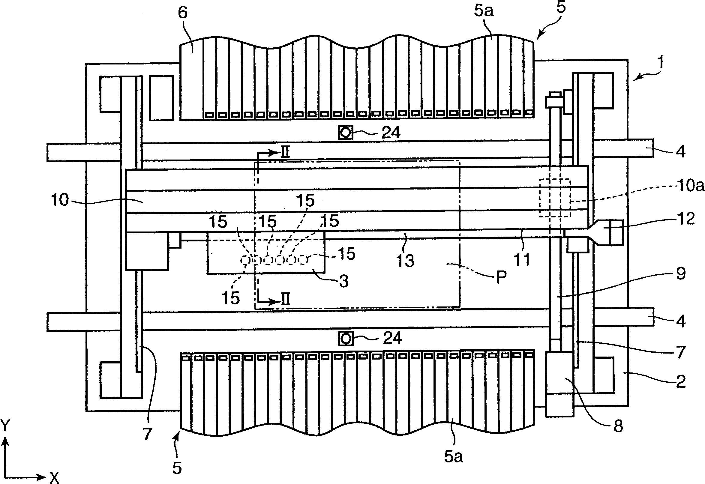
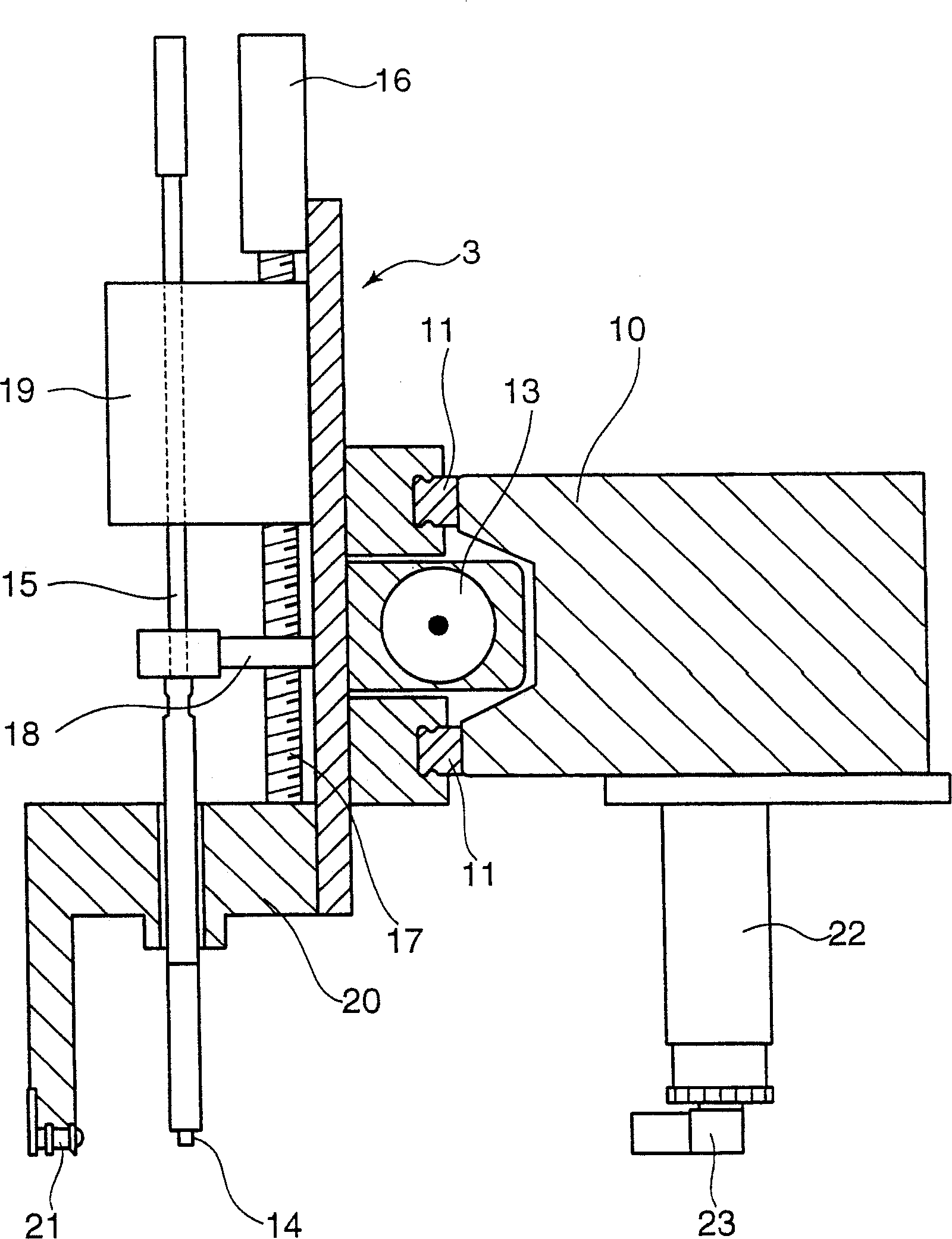
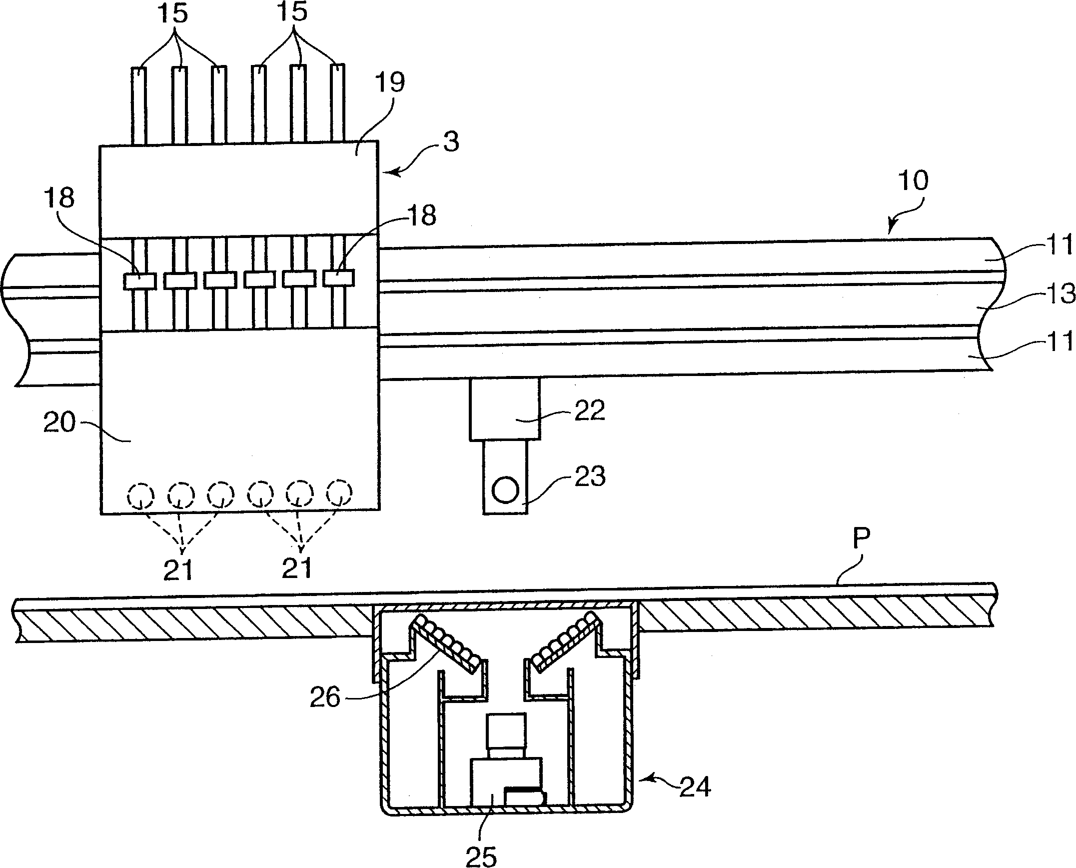
[0033] figure 1 Is a partial plan view of the surface mounting machine of the present invention, figure 2 Is omitted figure 1 A side cross-sectional view of part of the surface mount machine shown, image 3 Yes means omitted figure 1 A front cross-sectional view of a part of the surface mount machine shown.

[0034] The surface mounter mainly includes: the main body mechanism for mounting electronic components C (small chip components such as ICs, transistors, capacitors, etc.: refer to Figure 9(a)) on the printed circuit board P using the operation of each part of the mechanism 1; and the controller (control device) 30 (refer to Figure 4 ).

[0035] The main body mechanism 1 has a mounter body composed of a base 2 and the like, and a head unit (nozzle holding member) 3 that is movable relative to the mounter body.

[0036] The base 2 is provided with a convey...


PUM


Abstract

The invention provides a compact surface mounter capable of fast executing carryout detection of a sucking nozzle while suppressing damage to the sucking nozzle. A head unit 3 comprising a sucking nozzle for sucking an electronic component C displaces relative to a stage 2 on which a printed board P is placed, so that the electronic component C sucked by the sucking nozzle is mounted on the printed board P. The surface mounter comprises a support member 10 which supports the head unit 3 on the stage 2 so that the head unit 3 can displace along the X axis, a side camera capable of imaging the sucking nozzle sideways, on at least either the head unit 3 or the support member 10, and a controller for judging whether a component is sucked to the lower end part or not based on the side image of the electronic component C after the electric component is released.

Description

Technical field [0001] The present invention relates to a surface mounter that mounts electronic components such as IC chips on a printed wiring board. Background technique [0002] A generally known surface mount machine is a surface mount machine that is driven between an electronic component supply unit and a printed circuit board through a head having a suction nozzle, and the electronic components sucked by the supply unit are transported to the printed circuit board and mounted . [0003] Some surface mounters of this type can detect whether electronic components are left (whether the electronic components are brought back) on the nozzles that should have electronic components installed (for example, Patent Document 1: Japanese Patent Laid-Open No. 11-346100 No. disclosed electronic component mounting machine). [0004] The electronic component mounting machine has a sensor fixedly mounted on its main body, which can detect whether there is a suction nozzle at the lower end...

Claims


Application Information

Patent Timeline
IPC IPC(8): H05K13/04H05K13/02B65G47/91
Inventor 山田刚
Owner YAMAHA MOTOR CO LTD
Why Eureka
Try Eureka