Tubular busbar cutting device

A tubular busbar and cutting device technology, applied in metal processing and other directions, can solve the problems of inconvenient adjustment of cutting distance, inconvenient disassembly and use, inconvenient quick positioning, etc.

Active Publication Date: 2021-04-13
STATE GRID SHANDONG ELECTRIC POWER CO PINGYUAN POWER SUPPLY CO
View PDF5 Cites 1 Cited by
  • Summary
  • Abstract
  • Description
  • Claims
  • Application Information

AI Technical Summary

Problems solved by technology

[0005] The purpose of the present invention is to provide a tubular busbar cutting device to solve the problems of inconvenient adjustment of cutting distance, inconvenient quick positioning, poor safety protection effect and inconvenient disassembly and use in the above-mentioned background technology

Method used


Image

  • Tubular busbar cutting device
  • Tubular busbar cutting device
  • Tubular busbar cutting device

Examples


Embodiment Construction

[0029] The following will clearly and completely describe the technical solutions in the embodiments of the present invention with reference to the accompanying drawings in the embodiments of the present invention. Obviously, the described embodiments are only some, not all, embodiments of the present invention. Based on the embodiments of the present invention, all other embodiments obtained by persons of ordinary skill in the art without making creative efforts belong to the protection scope of the present invention.

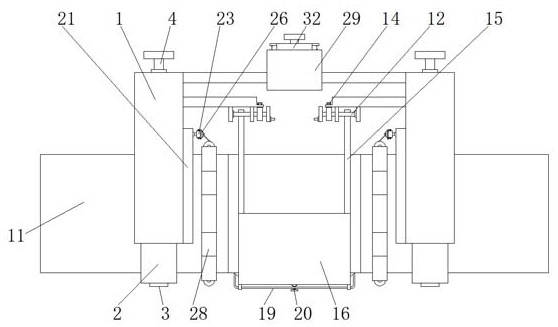
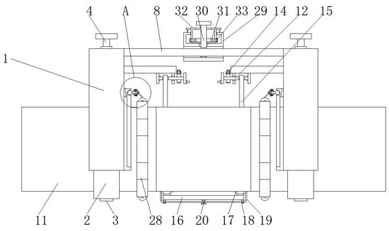
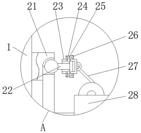
[0030] see Figure 1-7, the present invention provides a technical solution: a tubular busbar cutting device, including a fixed frame 1, a positioning shell 2, a guide roller 3, an operating rod 4, a first extrusion cylinder 5, an intermediate rod 6, a chain 7, an adjustment rope 8. Linkage rod 9, second extrusion cylinder 10, tubular busbar body 11, winding rod 12, positioning groove 13, positioning block 14, pull rope 15, support pad 16, suction cup 17, fixi...


PUM


Abstract

The invention belongs to the technical field of tubular busbar cutting, and particularly relates to a tubular busbar cutting device. The tubular busbar cutting device comprises a fixing frame and a tubular busbar body, a positioning shell is fixed to the inner side of the fixing frame, middle rods are arranged on the two sides of an operating rod, the tubular busbar body is arranged in the positioning shell, a winding rod is installed at the upper part of the fixing frame, a pull rope is fixed to the lower end of the winding rod, fixing rings are fixed to the two sides of the lower end of the supporting pad, and an annular movable frame is fixed to the lower part of the outer side of the fixing frame. According to the tubular busbar cutting device, the positioning shell is arranged on the outer side of the tubular busbar body in a sleeving mode from top to bottom, a guide roller guides the tubular busbar body, a pipe cutting machine is arranged on the outer side of the tubular busbar body in a sleeving mode, a rotating rod is rotated to wind an adjusting rope, the pipe cutting machine is moved to a proper cutting position, a limiting block and a fixing block are clamped, limiting of the positions of the rotating rod and the adjusting rope is achieved, and limiting and adjustment of the cutting position of the pipe cutting machine is further achieved.

Description

technical field [0001] The invention relates to the technical field of tubular busbar cutting, in particular to a tubular busbar cutting device. Background technique [0002] With the continuous development of the power transmission industry, it is often necessary to use tubular busbars to transmit grid power during the laying of the power grid. Among them, tubular busbars have the advantages of large carrying capacity, good insulation, low loss and strong resistance to electrical shocks. It is widely used. During the installation and maintenance of the tubular busbar, it is necessary to use cutting equipment to process the tubular busbar. [0003] The traditional tubular busbar cutting device has a single structure. When the cutting part of the tubular busbar needs to be cut and split, two cutting positions need to be acted on in sequence. It is not convenient to precisely calibrate and adjust the cutting distance during the process, and the cutting efficiency is low. More...

Claims


Application Information

Patent Timeline
Patent Type & Authority Applications(China)
IPC IPC(8): B26D7/26B26D7/01B26D7/02B26D7/00B26D1/28
CPCB26D7/2614B26D7/2628B26D7/01B26D7/018B26D7/02B26D7/00B26D1/28B26D2007/011B26D2007/013
Inventor 郑富强李辉梁晓李小雯张展于洋董艳芬李政高慧李富
Owner STATE GRID SHANDONG ELECTRIC POWER CO PINGYUAN POWER SUPPLY CO
Why Eureka
Try Eureka