
Needle board moving mechanism of computer knitting flat knitting machine

A technology of moving mechanism and flat knitting machine, which is applied in knitting, weft knitting, textile and paper making, etc. It can solve the problems of accuracy reduction of needle plate 5, wear of gears, increase of matching clearance, etc., and achieve accurate and reliable displacement, Guarantee the accuracy and protect the effect of the motor

Inactive Publication Date: 2009-11-18
JIANGSU JINLONG TECHNOLOGY CO LTD
View PDF0 Cites 4 Cited by
  • Summary
  • Abstract
  • Description
  • Claims
  • Application Information

AI Technical Summary

Problems solved by technology

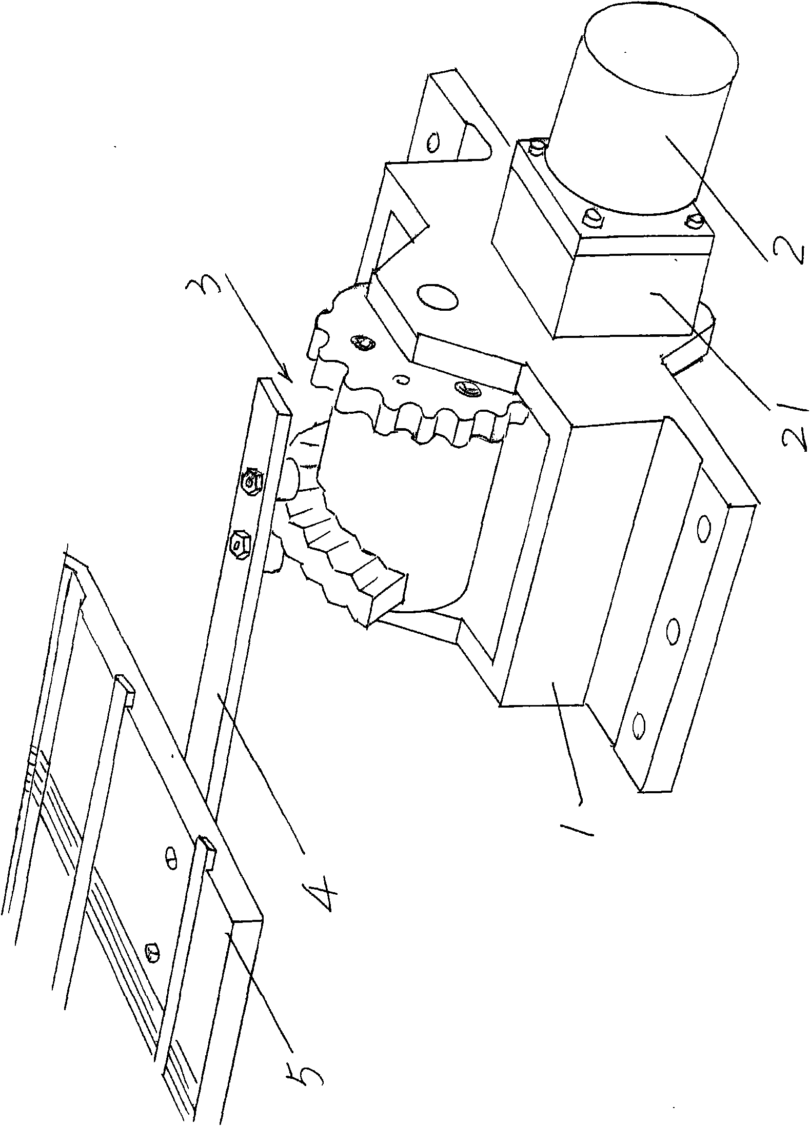
[0004] The above-mentioned needle plate moving mechanism has the following disadvantages: first, because the traction rod actuator 3 realizes the transmission connection with the gear on the output shaft of the reducer 21 through its large gear, there is inevitably a matching gap in the gear transmission, and the matching gap The larger the size, the worse the displacement positioning effect of the needle plate 5, especially, as the use time prolongs, the gears will wear out, and the matching gap will gradually increase, so that the accuracy of the movement of the needle plate 5 will gradually decrease, affecting the smooth progress of weaving. Secondly, frequent friction between a pair of rollers on the draw bar 4 and the convex curved surface of the cam of the draw bar actuator 3 will also affect the movement accuracy of the draw bar 4, so that the position of the needle plate 5 cannot be moved. Satisfy the degree of taking due date; in addition, it does not have a limit function, which is prone to over-travel work, causing the motor 2 to stop working and even causing the motor 2 to be damaged

Method used


Image

  • Needle board moving mechanism of computer knitting flat knitting machine
  • Needle board moving mechanism of computer knitting flat knitting machine

Examples


Embodiment Construction

[0019] In order to enable the examiners of the patent office, especially the public, to understand the technical essence and beneficial effects of the present invention more clearly, the applicant will describe in detail below in conjunction with the accompanying drawings in the form of embodiments, but none of the descriptions of the embodiments is a description of the present invention. Restriction of the inventive solution, any equivalent transformation made according to the concept of the present invention which is only in form but not in substance shall be regarded as the scope of the technical solution of the present invention.

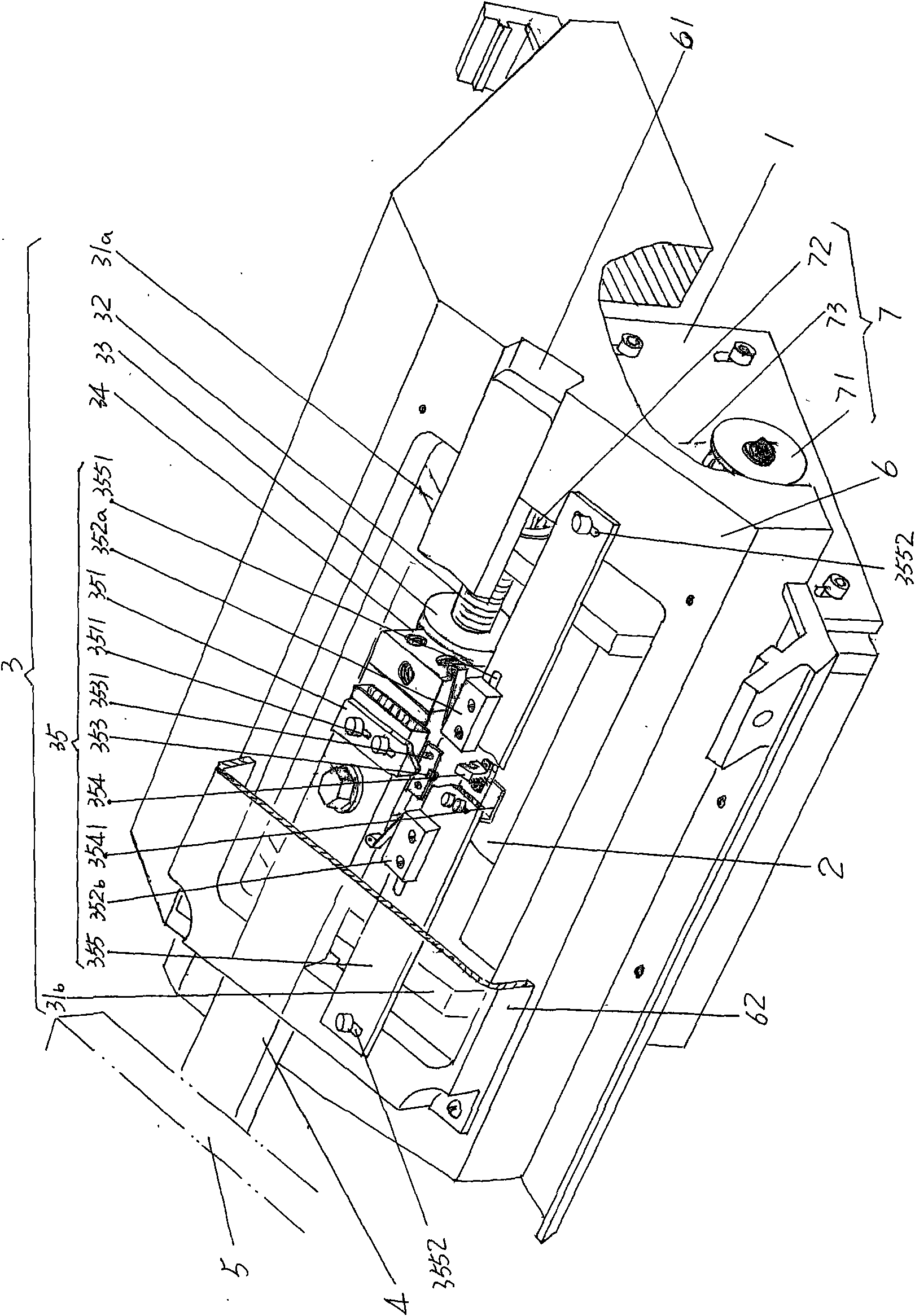
[0020] Please see figure 1 , provides the needle bed base 6 for shelving the needle plate 5 and doubles as the needle plate moving mechanism of the present invention. According to common sense, the needle plate 5 has a front needle plate and a rear needle plate, that is, a pair of needle plates 5. Although the applicant is in figure 1 Only on...


PUM


Abstract

The invention relates to a needle board moving mechanism of a computer knitting flat knitting machine, which belongs to the technical field of knitting machines. The needle board moving mechanism comprises a needle bed base, a motor base, a motor, a drawbar actuating device and a drawbar, wherein the drawbar actuating device comprises a first supporting seat, a second supporting seat, a g screw rod, a screw rod nut and a connecting block; the first supporting seat is fixed at one end of the needle bed base, the second supporting seat is fixed at the other end of the needle bed base, and the two supporting seats are parallel with each other; two ends of the screw rod are arranged on the first and the second supporting seats and are in driving connection with a driving device; the screw rod nut is arranged on the screw rod; the connecting block is fixed on the screw rod nut; the drawbar is fixedly connected with the connecting block; and the motor is electrically connected with an electric control device of the computer knitting flat knitting machine. The needle board moving mechanism has the advantages that the displacement of the needle board is accurate and reliable, and not only the motor can be protected but also the precision degree of the displacement of the needle plate is guaranteed.

Description

technical field [0001] The invention belongs to the technical field of knitting machinery, and in particular relates to a needle plate moving mechanism of a computerized flat knitting machine. Background technique [0002] As is well known in the industry, when computerized flat knitting machines knit fabrics, due to the requirements of patterns and styles, functions such as loop transfer and transfer need to be used during the knitting process, and even the knitting structure needs to be changed during the knitting process. To satisfy these functions, the needle board must be traversed. The so-called needle board traverse refers to changing the relative position of the front and rear needle boards as required. [0003] The needle plate moving mechanism of the known computerized flat knitting machine is driven by the motor so that the needle plate is displaced to meet the requirements of weaving and ensure the smooth completion of the knitted fabric. figure 2 The structure ...

Claims


Application Information

Patent Timeline
IPC IPC(8): D04B15/12
Inventor 金永良张和中兰先川海港
Owner JIANGSU JINLONG TECHNOLOGY CO LTD
Learn More