Light-emitting automobile sign and production process thereof

A technology for automobile signs and production technology, which is applied to optical signals, vehicle parts, signal devices, etc., can solve the problems of low pass rate of luminous automobile signs, achieve the effect of ensuring the appearance surface quality, high structural strength, and improving production efficiency

Pending Publication Date: 2021-04-13
NINGBO FULLSTATE AUTOMOBILE PARTS
View PDF5 Cites 0 Cited by
  • Summary
  • Abstract
  • Description
  • Claims
  • Application Information

AI Technical Summary

Problems solved by technology

[0004] In view of the above-mentioned related technologies, the inventor believes that the light-transmitting area in the above-mentioned luminous car signs is formed by removing the primer by a laser engraving machine. In the process of laser engraving, the qualified rate of luminous car signs is low

Method used


Image

  • Light-emitting automobile sign and production process thereof
  • Light-emitting automobile sign and production process thereof
  • Light-emitting automobile sign and production process thereof

Examples


Embodiment 1

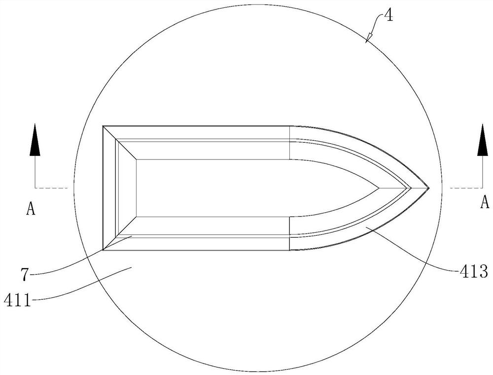
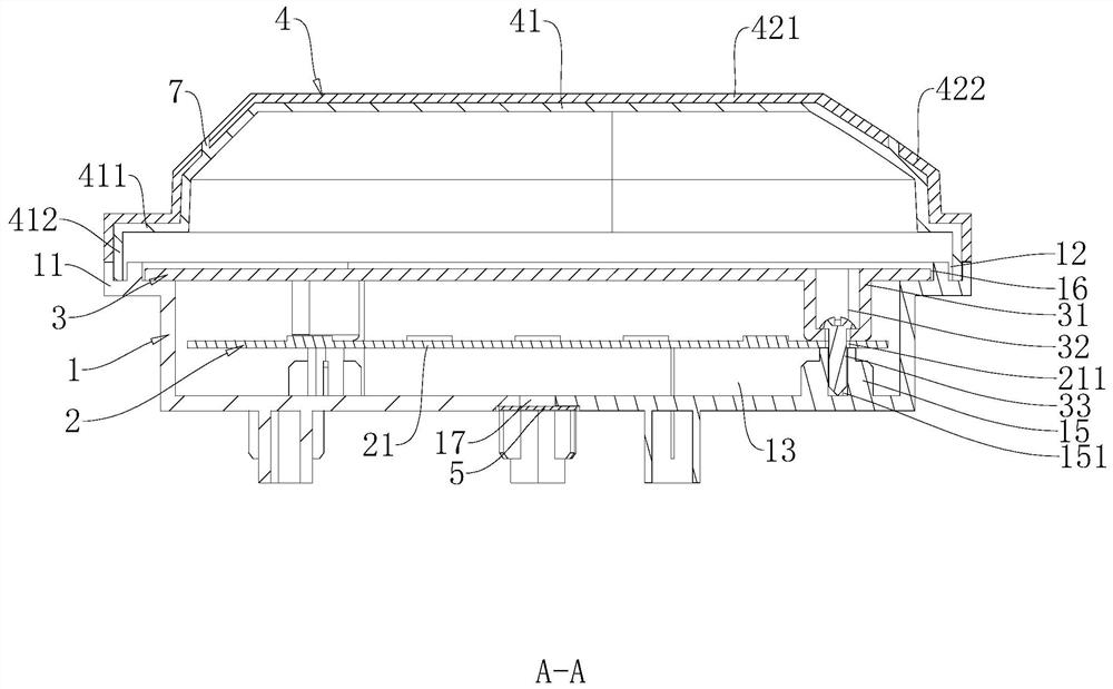
[0048] refer to figure 1 and figure 2 , The luminous automobile signboard includes a signboard base 1 , a light source part 2 , a uniform light plate 3 and a sign cover 4 .

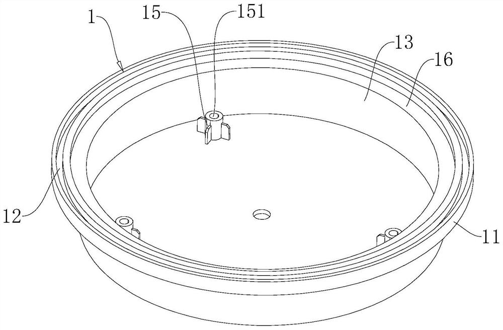
[0049] refer to figure 2 and image 3 , The sign base 1 is a hollow and cylindrical plastic seat. The sign base 1 is coaxially provided with an installation ring 11 for installing the sign cover 4 at the end close to the sign cover 4 . The mounting ring portion 11 is provided with a mounting ring groove 12 in the circumferential direction of the end surface facing the sign cover 4 .

[0050] refer to image 3 , The sign base 1 has a cylindrical installation cavity 13 . The installation cavity 13 is formed with an installation opening on the end surface of the sign base 1 close to the sign. The sign base 1 is vertically provided with three installation columns 15 on the bottom surface of the installation cavity 13 . The three installation columns 15 are evenly arranged around the axis of the sign...

Embodiment 2

[0067] refer to Figure 7 , this embodiment also discloses a luminous automobile signboard, which is different from the implementation of Example 1 in that: the outer surface 612 of the first outer cover of the first sign outer cover 421 is not provided with sign coating, and the outer surface of the second sign The outer surface 621 of the second outer cover of the cover 422 is not provided with logo coating, and the connection method between the logo outer cover and the transparent bottom cover 41 is not through laser transmission welding.

[0068] In this embodiment, the logo cover 4 is directly produced by a two-color injection machine, and the logo outer cover is fixed on the outer surface of the transparent bottom cover 41 during the production process.

Embodiment 3

[0070] refer to Figure 8 , this embodiment also discloses a luminous car sign, which is different from the embodiment of Example 1 in that: the position of the installation ring groove 12 in the sign base 1 and the installation flange of the sign base 1 and the transparent bottom cover 41 412 fixed way.

[0071] In this embodiment, the installation ring groove 12 of the signage base 1 is arranged at the edge of the end surface of the installation ring portion 11 facing the sign cover 4 . The installation flange 412 of the transparent bottom cover 41 can be inserted into the installation ring groove 12 , and the inner side wall of the installation flange 412 is attached to the annular side wall 121 of the installation ring groove 12 . Since the transparent bottom cover 41 is made of transparent PC and the sign base 1 is made of black PC, the installation flange 412 of the transparent bottom cover 41 and the annular side wall 121 of the installation ring groove 12 are connecte...


PUM


Abstract

The light-emitting automobile sign comprises a sign base, a light source piece and a sign cover installed on the sign base, and the sign cover comprises a transparent bottom cover and a sign outer cover welded to the outer surface of the transparent bottom cover. And the outer surface of the transparent bottom cover comprises a covering area for mounting the sign outer cover and a light-transmitting area for transmitting light of the light source part. The production efficiency of the light-emitting automobile sign is improved, and the percent of pass of the light-emitting automobile sign can be increased.

Description

technical field [0001] The application relates to the field of automobile signs, in particular to a luminous automobile sign and its production process. Background technique [0002] Car signs are usually installed on the front or rear of the car body to display the brand of the car. With the development of car signs, people have further requirements for the appearance of car signs, so luminous car signs came into being. [0003] Luminous car signs usually include a sign base, a light source and a sign cover. The logo cover is made of transparent material, and the inner surface of the logo cover is coated with a layer of opaque primer layer, and part of the primer in the primer layer is removed by a laser engraving machine to form a light-transmitting area of ​​the logo cover. Therefore, the light emitted by the light source can be emitted through the light-transmitting region. Among them, the light-transmitting area is mostly a light-transmitting ring arranged at the edg...

Claims


Application Information

Patent Timeline
Patent Type & Authority Applications(China)
IPC IPC(8): B60Q1/56B60R13/00
CPCB60R13/005B60Q1/56
Inventor 胡光远
Owner NINGBO FULLSTATE AUTOMOBILE PARTS
Why Eureka
Try Eureka