
Support for injection molding machine

A technology of injection molding machine and support column, which is applied in the direction of machine/stand, supporting machine, mechanical equipment, etc., can solve the problems of loose and damaged parts of injection molding machine, ground damage, vibration, etc., and achieve good shock absorption and buffering effect.

Pending Publication Date: 2021-04-13
衢州进盛塑料机械有限公司
View PDF0 Cites 0 Cited by
  • Summary
  • Abstract
  • Description
  • Claims
  • Application Information

AI Technical Summary

Problems solved by technology

[0003] At present, there are many problems in the use of injection molding machines. For example, when some existing injection molding machines are placed on the ground, the injection molding machine may directly cause damage to the ground. The looseness and damage of parts inside the injection molding machine affect the use

Method used


Image

  • Support for injection molding machine
  • Support for injection molding machine
  • Support for injection molding machine

Examples


Embodiment Construction

[0018] In order to enable those skilled in the art to better understand the solution of the present application, the technical solution in the embodiment of the application will be clearly and completely described below in conjunction with the accompanying drawings in the embodiment of the application. Obviously, the described embodiment is only It is an embodiment of a part of the application, but not all of the embodiments. Based on the embodiments in this application, all other embodiments obtained by persons of ordinary skill in the art without creative efforts shall fall within the scope of protection of this application.

[0019] It should be noted that the terms "first" and "second" in the description and claims of the present application and the above drawings are used to distinguish similar objects, but not necessarily used to describe a specific sequence or sequence. It should be understood that the data so used may be interchanged under appropriate circumstances for...


PUM


Abstract

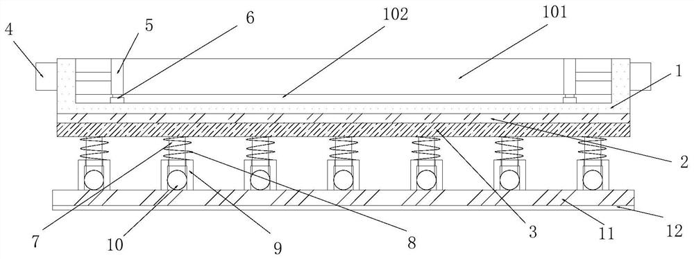
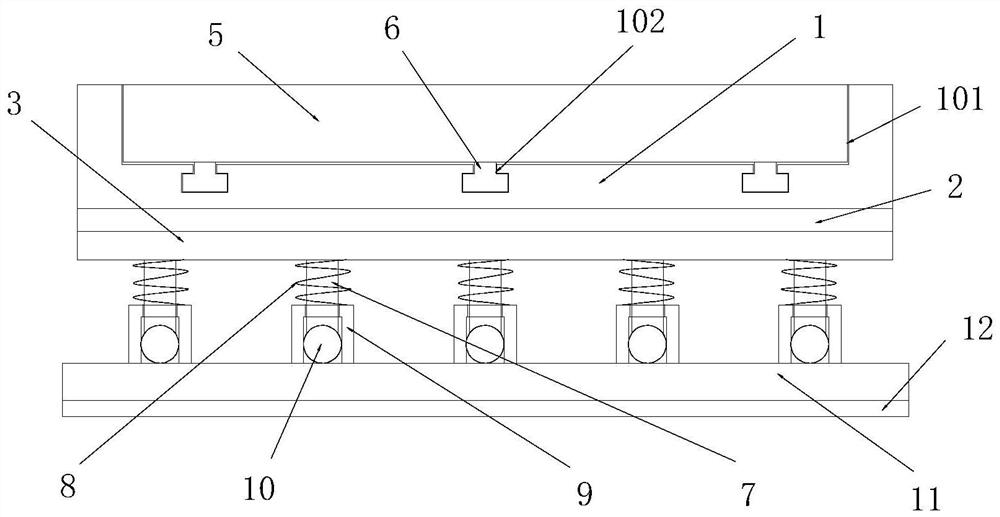
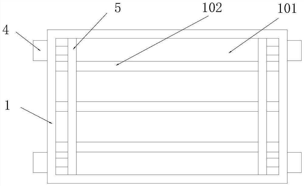
The invention discloses a support for an injection molding machine. The support comprises a containing seat, a containing groove, sliding grooves, a clamping and fixing mechanism and a damping and buffering mechanism, wherein the containing groove is formed in the surface of the top side of the containing seat, and the bottom side of the containing groove communicates with the sliding grooves formed in the surface of the bottom side of the containing seat; the clamping and fixing mechanism comprises an electric push rod, push plates and sliding blocks, the electric push rod is fixedly connected to the side surface of the containing seat, the output end of the electric push rod is fixedly connected with the push plates, the push plates are slidably connected into the containing groove, the sliding blocks are fixedly connected to the surfaces of the bottom sides of the push plates, and the sliding blocks are slidably connected into the sliding grooves; and the damping and buffering mechanism comprises a rubber damping pad, a fixing seat, supporting columns, supporting cylinders, damping springs, elastic damping balls, a base and antiskid lines, the rubber damping pad is fixedly connected to the surface of the bottom side of the containing seat, and the fixing seat is fixedly connected to the surface of the bottom side of the rubber damping pad. The support for the injection molding machine is novel in design and simple in structure.

Description

technical field [0001] The application relates to a bracket for an injection molding machine, in particular to a bracket for an injection molding machine. Background technique [0002] Injection molding machine is also known as injection molding machine or injection machine; it is the main molding equipment for making thermoplastics or thermosetting plastics into various shapes of plastic products using plastic molding molds; the injection molding machine can heat the plastic and apply high pressure to the molten plastic to make it eject And it is full of mold cavity; Injection molding machine is also called injection molding machine or injection machine, many factories are called beer machine, and injection products are called beer pieces; it is a process of making plastic products of various shapes from thermoplastic or thermosetting materials using plastic molding molds. Main molding equipment; Injection molding machines can be divided into vertical type, horizontal type ...

Claims


Application Information

Patent Timeline
IPC IPC(8): F16F15/08F16F15/04F16M11/04B29C45/17
CPCB29C45/17B29C2045/1784F16F15/046F16F15/085F16M11/04
Inventor 方景飞
Owner 衢州进盛塑料机械有限公司
Learn More