
Air massager

A massager and air technology, which can be applied in the directions of kneading massage appliances, auxiliary products for massage, heating appliances for treatment and treatment, etc., can solve the problem that the toe part cannot obtain sufficient massage effect and the like

Inactive Publication Date: 2003-11-05
MARUTAKA CO LTD
View PDF0 Cites 0 Cited by
  • Summary
  • Abstract
  • Description
  • Claims
  • Application Information

AI Technical Summary

Problems solved by technology

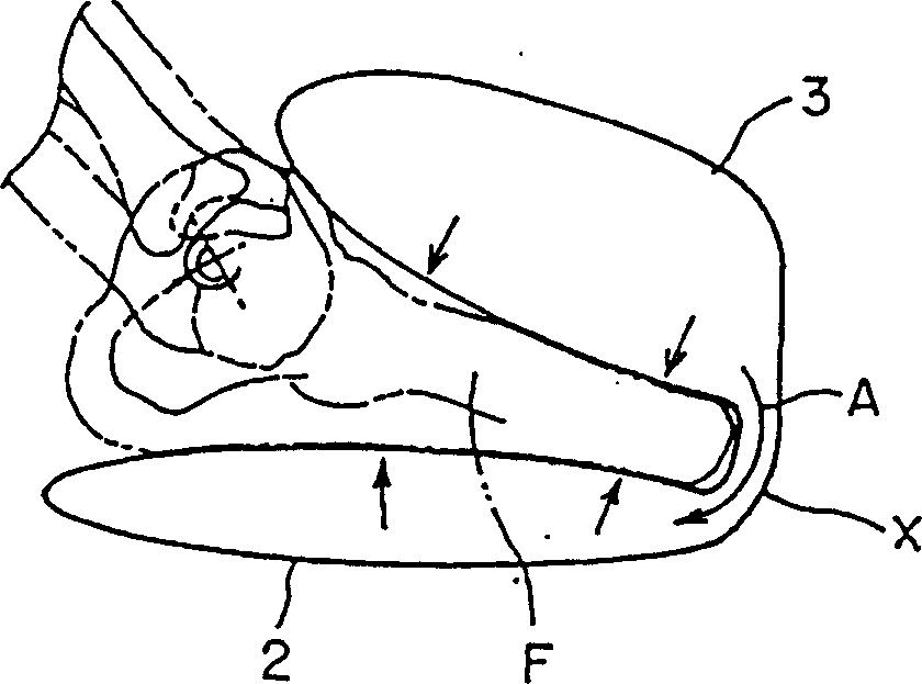
[0007] As mentioned above, in the known air massager, such as Figure 10 As shown, when the air bag A4 arranged on the dorsal side of the foot and the air bag A5 arranged on the plantar side are filled with pressurized air to expand, because these air bags A4 and A5 expand into ellipses with P1 and P2 as the expansion centers respectively Due to the cross-sectional shape, there are gaps S1 and S2 between the air pockets A4 and A5 on the toe side and the foot F, and there is a problem that a sufficient massage effect cannot be obtained at the toe

Method used


Image

  • Air massager
  • Air massager
  • Air massager

Examples


Embodiment Construction

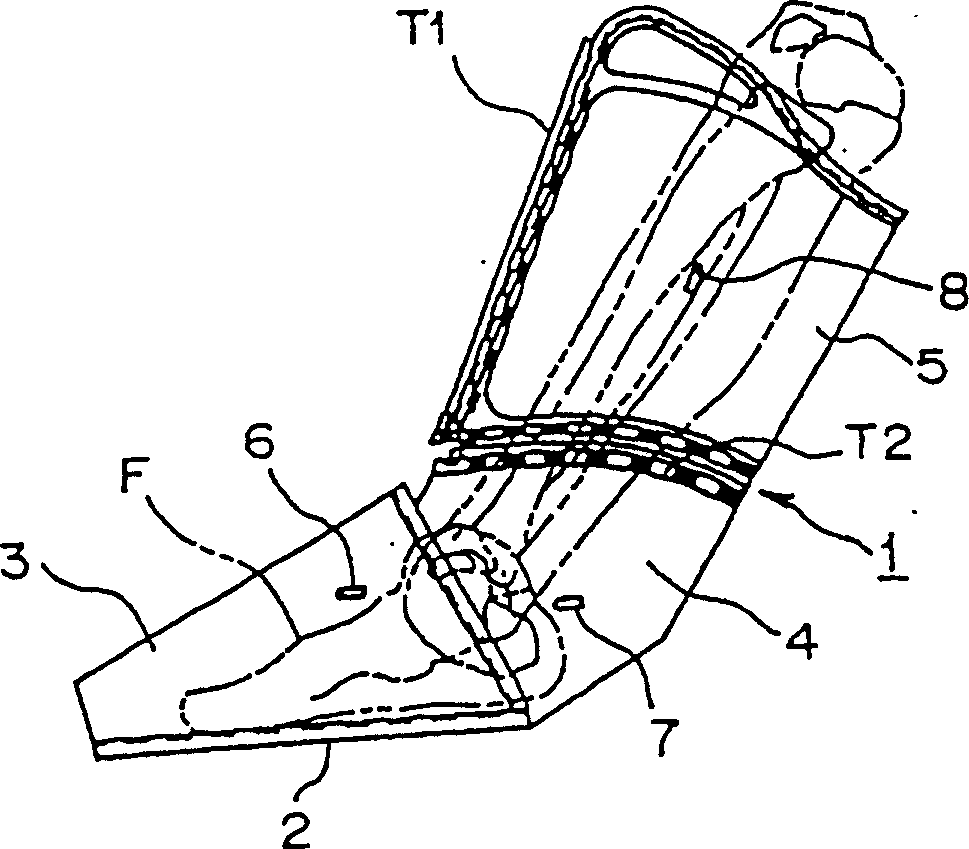
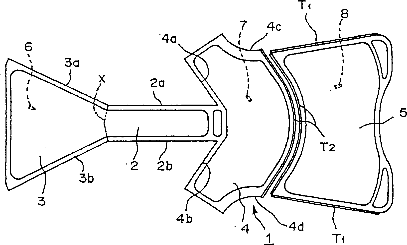
[0026] figure 1 It is a side view showing Embodiment 1 of an air massager (hereinafter referred to as a massager) of the present invention, figure 2 is the composition figure 1 The plane expansion diagram of the air bag body of the air massager shown, such as figure 1 , 2 As shown, the massager 1 has a plantar side air bag 2 for compressing the bottom side of the foot F, a foot dorsum side air bag 3 for pressing the dorsal side of the foot, and compresses the foot by wrapping the heel from the left and right sides. The foot neck side air bag 4 of the neck part and the calf side air bag 5 for compressing the calf.

[0027] like figure 2 As shown, the seams 4a, 4b on both sides of the air bag 4 on the neck side of the massager 1 are sewed with the seams 2a, 2b on the left and right sides of the air bag 2 on the plantar side respectively, and the parts near the heel are sewed, and the air on the dorsal side of the foot The seams 3a, 3b on the left and right sides of the...


PUM


Abstract

Provided is an air pressure massager which can effectively massage the toe without creating a gap between the toe side and the foot when the air bag on the sole side and the air bag on the dorsal side of the foot are compressed to expand. This massager massages the foot F by pressing an air bag inflated with pressurized air supplied from an external air source.

Description

technical field [0001] The present invention relates to an air massager for massaging feet which is constituted by an air bag inflated by pressurized air supplied from an external air source and utilizes the air bag to expand and contract. Background technique [0002] like Figure 8 and 9 The shown existing air massager for massaging feet is known. [0003] This massager A1 is that a plurality of air bags A2, A3, A4 and A5 are connected into a long boot shape by sewing, and has a structure that can complete the following functions: by separating from the massager A1 and being arranged on the outside and not shown in the figure An air supply source such as a pump is shown to supply pressurized air through an air line to inflate the air bags, and then to deflate the air bags A2, A3, A4, and A5 by discharging air from the air bags A2, A3, A4, and A5. [0004] When using the massager A1 to massage the feet, open the fastener A6 mounted on the upper central part (only on the ...

Claims


Application Information

Patent Timeline
IPC IPC(8): A61H7/00A61F7/00A61F9/00A61HA61H9/00
Inventor 古川洋一青木正亘青木干享
Owner MARUTAKA CO LTD
Learn More