Intelligent shoe cabinet

A shoe cabinet, intelligent technology, applied in the cleaning of cabinets, wardrobes, boots and shoes, etc., can solve the problem that the integrated function of cleaning, maintenance, storage, transportation and taking out shoes cannot be realized, the shoe cabinet does not automatically release shoes, and the interior of the automatic storage is automatic. Problems such as transmission and poor experience

Pending Publication Date: 2021-04-16
深圳市金博奥科技有限公司
View PDF11 Cites 4 Cited by
  • Summary
  • Abstract
  • Description
  • Claims
  • Application Information

AI Technical Summary

Problems solved by technology

The shoe cabinet does not have the functions of automatic shoe release, automatic storage and internal automatic transmission, which will be very inconvenient for the disabled or the elderly with limited mobility
At the same time, traditional shoe cabinets cannot realize the integrated functions of cleaning and maintenance, st...

Method used


Image

  • Intelligent shoe cabinet
  • Intelligent shoe cabinet
  • Intelligent shoe cabinet

Examples


Embodiment 1

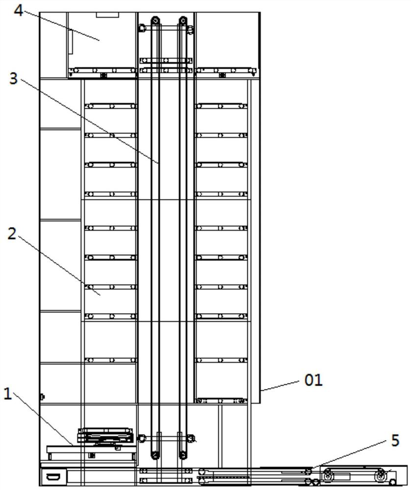
[0097] like Figure 10 As shown, in the first embodiment, the console 11 is specifically an assembly of the console 11 that integrates the functions of lifting, rotating, and translating, and specifically includes a horizontal transmission mechanism 111, a lifting mechanism 112, a rotating mechanism 113, and a horizontal sliding mechanism. Shifting mechanism 114 and longitudinal sliding mechanism 115. Wherein, the horizontal transmission mechanism 111 is used for moving the shoes to be cleaned in the horizontal direction, and the longitudinal sliding mechanism 115 is used to drive the shoes to be cleaned to move in the vertical direction, and the vertical sliding mechanism 115 is located below the horizontal transmission mechanism 111 . A lifting mechanism 112 , a rotating mechanism 113 and a lateral sliding mechanism 114 are arranged in sequence from top to bottom between the horizontal transmission mechanism 111 and the longitudinal sliding mechanism 115 . The lifting mecha...

Embodiment 2

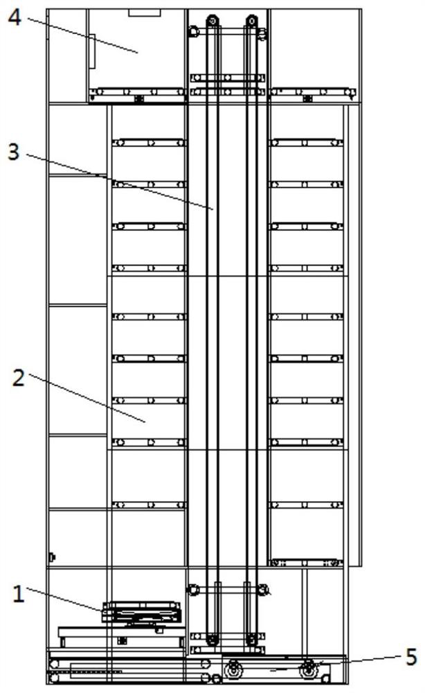
[0106] like Figure 11 As shown, in the second embodiment, the console 11 uses a horizontal transmission mechanism 111 and a liftable vertical transmission mechanism 1113 to realize the delivery of shoes. Unlike the horizontal transmission mechanism 111 in the first embodiment, this implementation The horizontal transfer mechanism 111 in the example is provided with a plurality of cleaning rollers 1111 arranged side by side and a cleaning roller motor 1112 corresponding to the cleaning rollers 1111. The cleaning roller motor 1112 is used to drive the cleaning roller 1111 to rotate; the longitudinal transfer mechanism 1113 is specifically A vertical conveyor belt mechanism or a slide bar mechanism that can be lifted, and the vertical conveyor belt mechanism or the slide bar mechanism is connected with a jacking mechanism, and the jacking mechanism is used to lift the vertical conveyor belt mechanism or the slide bar mechanism so as to push the shoes to be cleaned away from the c...

Embodiment 3

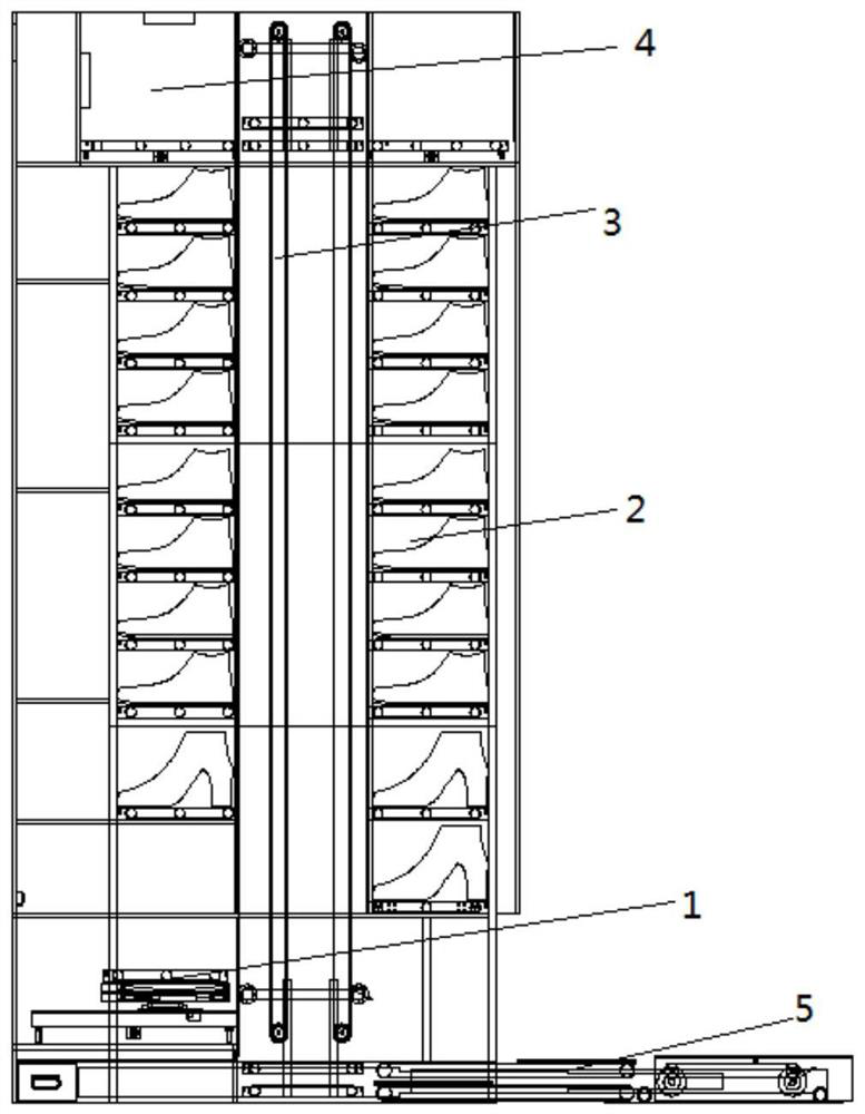
[0110] like Figure 12 As shown, in the third embodiment, the cleaning chamber 10 is provided with a plurality of second manipulators 12211 fixed by the second base 12212. The second manipulators 12211 have multi-dimensional mobility, and the second manipulators 12211 can adopt industrial six-axis The mechanical arm can deliver the cleaning head 121 to any place on the outer surface of the shoe to realize the cleaning operation.

[0111] The console 11 adopts a combined structure of a horizontal transmission mechanism 111 and a vertical sliding mechanism 115, wherein the horizontal transmission mechanism 111 is specifically a conveyor belt mechanism, and the structure of the conveyor belt mechanism can refer to the conveyor belt mechanism in the first embodiment; The arrangement of the mechanism 115 can also refer to the longitudinal sliding mechanism 115 in the first embodiment. The horizontal transmission mechanism 111 is arranged above the longitudinal sliding mechanism 11...


PUM


Abstract

The invention discloses an intelligent shoe cabinet. The intelligent shoe cabinet comprises a cabinet body and an output module movably connected to the cabinet body and used for conducting telescopic movement in the horizontal direction relative to the cabinet body; a cleaning module, a storage module and a lifting conveying module are arranged in the cabinet body; the cleaning module is used for cleaning and maintaining shoes to be cleaned; the storage module is used for storing the cleaned shoes; the output module, the cleaning module and the storage module can all convey the shoes in the transverse direction; the lifting conveying module can move in the vertical direction and allows the shoes to be conveyed among the cleaning module, the storage module and the output module. According to the intelligent shoe cabinet, the operation procedures of cleaning, shoe storing and shoe taking of a user can be simplified, the cleaning effect can be improved, and the risk that the disabled or the old with mobility difficulties are injured due to actions such as stooping can be avoided; meanwhile, the intelligent shoe cabinet can also realize full-automatic service of shoes, including suggestions for use, cleaning, daily maintenance and the like.

Description

technical field [0001] The invention relates to the technical field of smart home, in particular to a smart shoe cabinet. Background technique [0002] At present, the shoe cabinets on the market still need manual operation when taking and putting shoes. When storing shoes, the user needs to take off the shoes first, and then manually put the shoes into the shoe cabinet; when picking up the shoes, the user also needs to manually remove the shoes from the shoe cabinet. The shoe cabinet does not have the functions of automatic shoe release, automatic storage, and internal automatic transmission, which will be very inconvenient for the disabled or the elderly with limited mobility. At the same time, traditional shoe cabinets cannot realize the integrated functions of cleaning and maintenance, storage, transportation and taking out shoes, which will lead to poor user experience. [0003] Therefore, how to avoid the inability of traditional shoe cabinets to integrate the functi...

Claims


Application Information

Patent Timeline
IPC IPC(8): A47L23/02A47L23/20A47B61/04A61L2/10A61L2/20A61L2/24A61L2/26A61L101/10
Inventor 涂晋熙涂勇
Owner 深圳市金博奥科技有限公司
Why Eureka
Try Eureka