USB socket and manufacturing method thereof

A technology of plug and contact parts, which is applied to contact parts, fixed/insulating contact members, protective grounding/shielding devices of connecting parts, etc., which can solve complex processes, damage to the socket end, and the inability of the tongue to be inserted into the cavity of the plug. and other problems to achieve the effect of ensuring wear resistance and reducing manufacturing costs

Pending Publication Date: 2021-04-16
JUST CONNECTOR KUSN
View PDF0 Cites 3 Cited by
  • Summary
  • Abstract
  • Description
  • Claims
  • Application Information

AI Technical Summary

Problems solved by technology

[0002] The traditional USB interface needs to be plugged in the specified direction. For example, the Micro USB interface, the corresponding plug and socket need to be docked according to the established docking direction, and the structure size is very small, and the plastic structure is not strong enough. When the user plugs in, it is easy. Even if there is an anti-mis-insertion design, if some users forcefully insert it incorrectly, it will still cause irreversible damage to the socket end in the electronic device. For example, the docking tongue plate is damaged and the whole shifts, resulting in the docking tongue cannot be inserted into the cavity of the plug. Realize docking, even if the tongue plate is damaged by repeated wrong plugging and unplugging, the socket terminal on the tongue plate will break and completely lose the charging and signal transmission functions
The Type C USB socket solves the problem of the traditional Micro USB interface and realizes the compatibility of positive and negative insertion. However, in order to adapt to the miniaturization of electronic equipment, the Type C connector is still small in size and structure, and the internal functions that need to be implemented are more powerful. , the full version of the Type C interface needs to set up to 24Pin independent terminals on the upper and lower sides. Process, the existing process generally adopts three-time injection molding process, for example, first, the metal middle plate and one row of terminal groups are injection-molded as one, and the other row of terminal groups is injection-molded as one, and then the two are superimposed into one again Injection molding is integrated; finally, in order to cut the tape at the front end of the terminal group, injection molding is required again to wrap the end edge
With so many injection molding processes, the manufacturing cost of products remains high and it is difficult to adapt to the highly competitive market

Method used


Image

  • USB socket and manufacturing method thereof
  • USB socket and manufacturing method thereof
  • USB socket and manufacturing method thereof

Examples


Embodiment 1

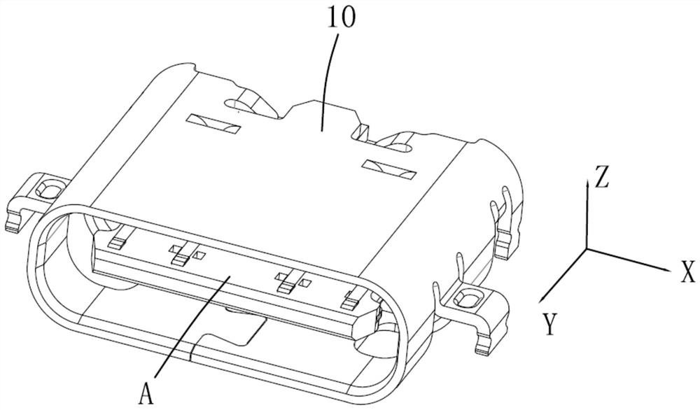
[0036] This application starts with figure 1 The X direction shown is the left-right direction (lateral direction), the Y direction is the front-rear direction (longitudinal direction), and the Z direction is the vertical direction.

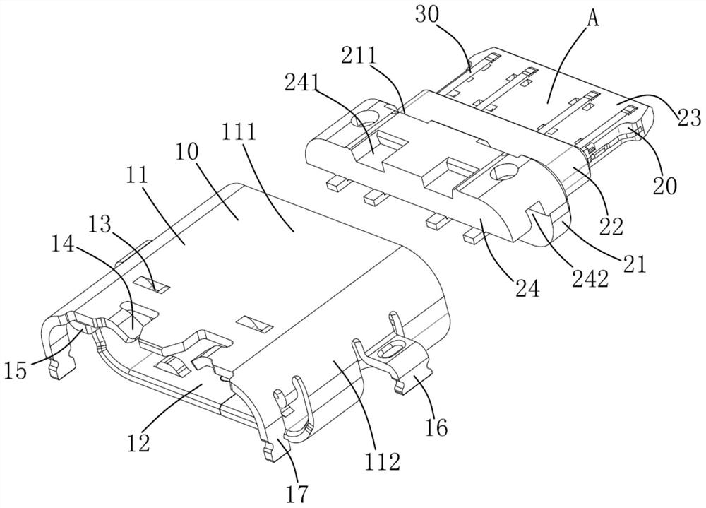
[0037] see figure 1 , figure 2 As shown, the USB socket of the present application is a Type C USB socket, which supports forward and reverse plugging and unplugging. The USB socket of the present application includes a connector A and a metal casing 10 sleeved outside the connector A.

[0038] The metal shell 10 includes a cylindrical body 11 , a cavity 12 surrounded by the cylindrical body 11 , and first and second welding legs 16 and 17 punched from the cylindrical body 11 .

[0039] The cylindrical body 11 includes vertical cylindrical walls 111 on upper and lower sides and a lateral cylindrical wall 112 connecting the vertical cylindrical walls 111 in the lateral direction. The rear end of the vertical cylinder wall 111 is punched and f...

Embodiment 2

[0050] please continue Figure 9 As shown, it is a cross-sectional view of the ground terminal 31 according to the second embodiment of the present application. Compared with the first embodiment, the thinned portion 314 ′ of the ground terminal 31 of this embodiment is bent toward the side of the metal reinforcement 33 . The second plate body portion 332 is provided with a buckle hole 4 on one lateral side, and the thin portion 314 ′ of the ground terminal 31 passes through the buckle hole 4 and then abuts against the second plate body portion 332 on the leading edge 5 surface. The buckle hole 4 can be opened from the lateral inner side or the outer side, and the ground terminal 31 is inserted from the lateral opening direction of the buckle hole 4 . This design can enhance the firmness between the metal reinforcing member 33 and the ground terminal 31 and improve the contact performance.

[0051] The manufacturing method of the USB socket of the present application compris...


PUM


Abstract

The invention provides a USB socket, and the socket comprises a plug connector and a metal shell sleeved outside the plug connector. The plug connector comprises a terminal group and an insulating body for fixedly holding the terminal group into a whole, and the insulating body comprises a base part, a wrapping part formed by extending forwards from the base part and a butt joint tongue part formed by extending forwards from the wrapping part; the terminal group at least comprises a pair of grounding terminals located at the outermost side and a pair of power supply terminals located between the grounding terminals. Each power supply terminal comprises an embedded part embedded into the insulating body, a welding pin formed by extending backwards from the embedded part, a first contact part which extends forwards from the embedding part and the surface of which is exposed out of the vertical first side surface of the butt-joint tongue part, and a second contact part which is bent reversely from the front end of the first contact part and extends backwards to form the surface of the second contact part and the surface of which is exposed out of the vertical second side surface of the butt-joint tongue part. The manufacturing cost can be effectively reduced.

Description

technical field [0001] The invention relates to the field of electrical connectors, in particular to a USB socket and a manufacturing method thereof. Background technique [0002] The traditional USB interface needs to be plugged in the specified direction, such as the Micro USB interface, the corresponding plug and socket need to be connected in the established docking direction, and the structure size is very small, and the plastic structure strength is insufficient. Even if there is an anti-mis-insertion design, if some users forcefully insert it incorrectly, it will still cause irreversible damage to the socket end in the electronic device. For example, the docking tongue plate is damaged and displaced as a whole, causing the docking tongue to be unable to be inserted into the cavity of the plug. To achieve docking, even after repeated wrong plugging and unplugging causes damage to the tongue plate, the socket terminals on the tongue plate will be broken and the charging...

Claims


Application Information

Patent Timeline
Patent Type & Authority Applications(China)
IPC IPC(8): H01R13/40H01R13/652H01R13/02
CPCH01R13/02H01R13/40H01R13/652
Inventor 唐敏杨伟
Owner JUST CONNECTOR KUSN
Why Eureka
Try Eureka