Vehicular door frame
A frame and door technology, which is applied to doors, vehicle parts, transportation and packaging, etc., can solve the problems that it is difficult to ensure the rigidity and strength of welded parts
- Summary
- Abstract
- Description
- Claims
- Application Information
AI Technical Summary
Problems solved by technology
Method used
Image
Examples
no. 1 Embodiment approach
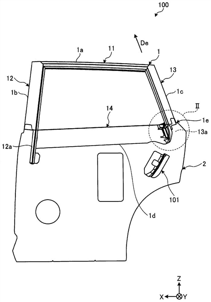
[0026] figure 1 It is a side view of the rear door 100 viewed from the inside in the vehicle width direction. Such as figure 1 As shown, the rear door 100 includes a rear door frame 1 and a door panel 2 .
[0027] The rear door frame 1 has an upper frame 11 , a front pillar 12 , a rear pillar 13 and a waist reinforcement 14 . The upper frame 11 constitutes the upper edge 1a of the opening for the window panel, the front pillar 12 constitutes the front edge 1b of the opening, the rear pillar 13 constitutes the rear edge 1c of the opening, and the waist reinforcement 14 constitutes the lower edge 1d of the opening. The rear door frame 1 is an example of a door frame.
[0028] The upper frame 11 , the front pillar 12 , the rear pillar 13 , and the waist reinforcement 14 are made of metal materials such as aluminum alloy and iron-based materials, for example. The rear pillar 13 can be formed by extrusion molding of aluminum alloy, for example. Additionally, the lumbar reinfor...
no. 2 Embodiment approach
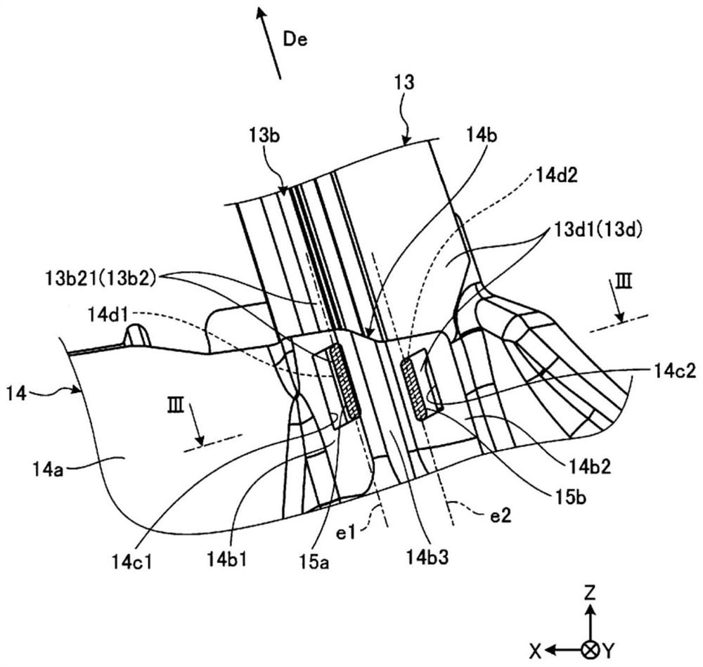
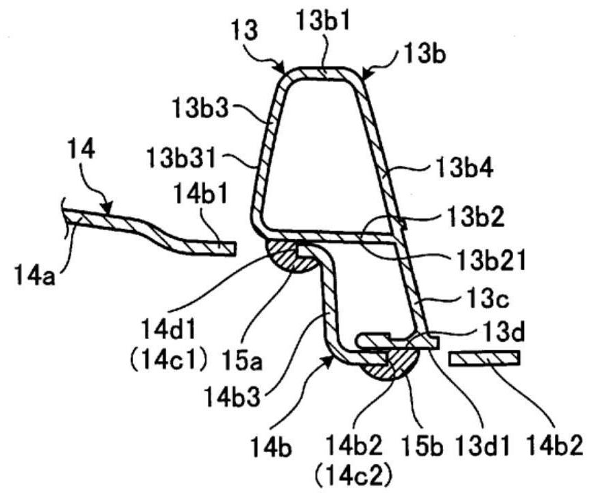
[0044] Figure 4 The rear door frame 1 of the second embodiment is viewed from the inside in the vehicle width direction figure 1 Perspective view of Part II of Figure 5 yes Figure 4 The V-V section view.
[0045] In the present embodiment, instead of the two openings 14c1 and 14c2, one opening 14c3 may be provided in the mounting portion 14b. The opening portion 14c3 is a notch opened downward from the upper edge 14e of the attachment portion 14b.
[0046] The front part 14b1 of the mounting part 14b is adjacent to the front of the front surface 13b31 of the front wall 13b3 of the rear pillar 13, and the rear end (rear edge) of the front part 14b1, that is, the edge 14d1 on the front side of the opening 14c3 is in contact with the front surface 13b31. Abut. In such a structure, the front edge 14d1 is welded to the front surface 13b31. The bead 15a generated by this welding extends approximately along the edge portion 14d1, in other words approximately along the direct...
no. 3 Embodiment approach
[0053] Figure 6 The rear door frame 1 of the third embodiment is viewed from the inside in the vehicle width direction figure 1 Perspective view of Part II of the Figure 7 yes Figure 6 Sectional view of VII-VII, Figure 8 yes Figure 6 Sectional view of VIII-VIII.
[0054] In the present embodiment, two openings 14c4, 14c5 connected to each other are provided in the attachment part 14b instead of the openings 14c1, 14c2, 14c3. The opening 14c4 is a notch formed by opening the upper corner of the mounting part 14b, and the opening 14c5 is a slit-shaped notch opened downward from the lower edge 14c41 of the opening 14c4.
[0055] Similar to the second embodiment, in this embodiment, the front portion 14b1 of the mounting portion 14b is adjacent to the front of the front surface 13b31 of the front wall 13b3 of the rear pillar 13, and the rear end (rear edge) of the front portion 14b1 is open in other words. An edge portion 14d1 on the front side of the portion 14c4 is in...
PUM
 Abstract
Description
Claims
Application Information
 - R&D
- Intellectual Property
- Life Sciences
- Materials
- Tech Scout
- Unparalleled Data Quality
- Higher Quality Content
- 60% Fewer Hallucinations
Browse by: Latest US Patents, China's latest patents, Technical Efficacy Thesaurus, Application Domain, Technology Topic, Popular Technical Reports.
© 2025 PatSnap. All rights reserved.Legal|Privacy policy|Modern Slavery Act Transparency Statement|Sitemap|About US| Contact US: help@patsnap.com


