
Method of producing screw device, and screw device

A manufacturing method and thread technology, applied in the direction of transmission, belt/chain/gear, mechanical equipment, etc., can solve the problem of difficulty in ensuring the strength of the ball screw nut, and achieve the effects of dimensional stability, productivity improvement, and strength improvement

Active Publication Date: 2010-08-11
THK CO LTD
View PDF2 Cites 0 Cited by
  • Summary
  • Abstract
  • Description
  • Claims
  • Application Information

AI Technical Summary

Problems solved by technology

However, on the contrary, it is difficult to ensure the strength of the ball screw nut

Method used


Image

  • Method of producing screw device, and screw device
  • Method of producing screw device, and screw device
  • Method of producing screw device, and screw device

Examples


Embodiment Construction

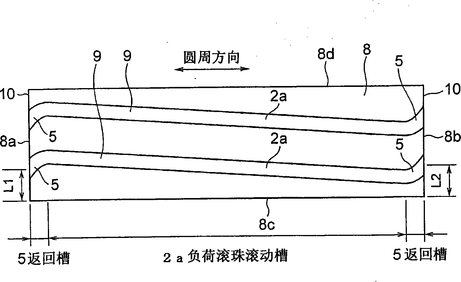
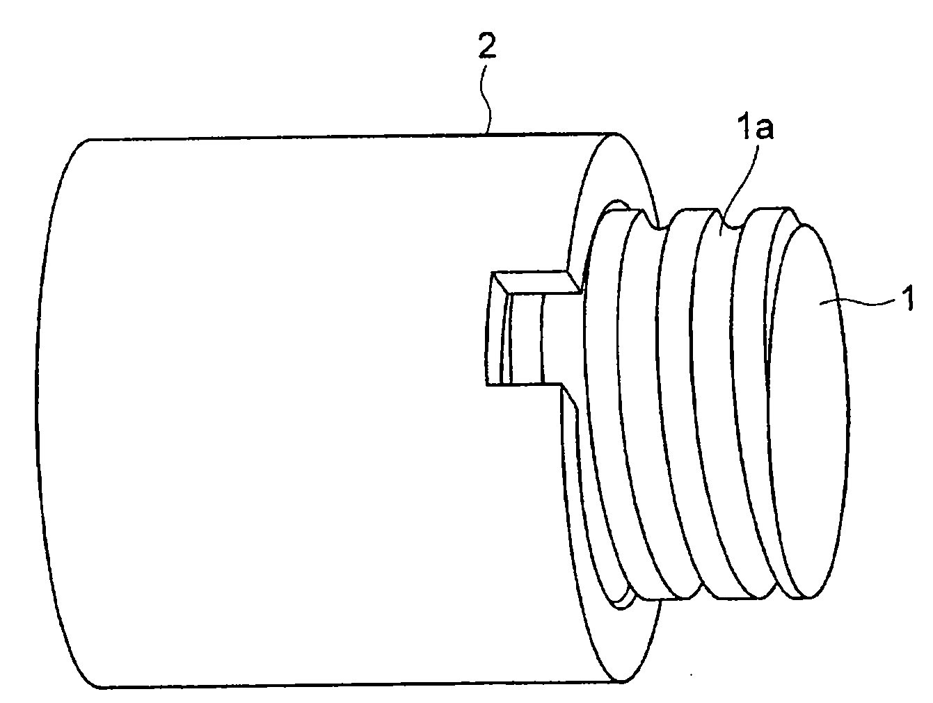
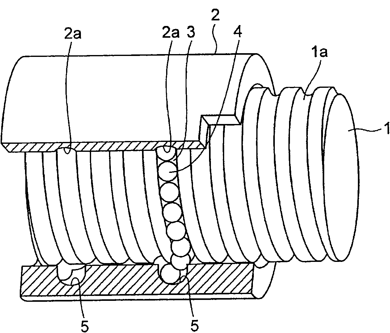
[0042] Hereinafter, embodiments of the present invention will be described in detail based on the drawings. Fig. 1 and Fig. 2 show a screw device according to an embodiment of the present invention. Fig. 1 shows a perspective view of the screw device, and Fig. 2 also shows a perspective view of the screw device (including a partial cross section). The screw device aligns the rolling element rolling groove 1a of the threaded shaft 1 and the load rolling element rolling groove 2a of the nut 2 at the same position, and the resulting rolling element rolling path 3 incorporates balls 4 as rolling elements.

[0043] A ball rolling groove 1a is formed on the outer peripheral surface of the threaded shaft 1, and the ball rolling groove 1a has a predetermined pitch as a spiral rolling element rolling groove. The cross-sectional shape of the ball rolling groove 1a is formed into a so-called gothic arch groove shape by combining two arcs. The ball 4 and the ball rolling groove 1a contact ...


PUM


Abstract

A method of producing a screw device, having high productivity and capable of achieving sufficient strength of a nut. The method of producing a screw device has a groove forming step for previously forming a load ball rolling groove in a flat plate, which step is followed by a nut forming step for forming a nut by bending the flat plate into a ring. Since the method has, after the groove forming step in which the load rolling groove is formed in the flat plate, the nut forming step in which the flat plate is bent into a ring, sufficient strength of the nut can be easily achieved, and in addition, high compression stress is left in the load ball rolling groove in the inner diameter surface of the nut.

Description

Technical field [0001] The invention relates to a threaded device in which rolling bodies are interposed between a threaded shaft and a nut and can perform rolling motion. Background technique [0002] In the process of generalization of electric power steering devices, thinner nuts and simplification of cycle manufacturing are increasingly required. The current trend is that a deflector type ball screw has become the mainstream. In the ball screw of the deflector method, a deflector (also called a "block") is embedded in the nut to circulate the balls. The deflector forms a load connected to less than one circle. Return grooves at both ends of the ball rolling groove. In addition, the return groove of the deflector causes the balls rolling in the spiral load ball rolling groove around the threaded shaft to pass the thread of the threaded shaft before turning around the threaded shaft and return to the front of this circle. The ball rolling groove. [0003] From the viewpoint o...

Claims


Application Information

Patent Timeline
Patent Type & Authority Patents(China)
IPC IPC(8): F16H25/24
CPCF16H2025/2481F16H25/2223F16H25/24Y10T74/19744Y10T29/49636Y10T29/49673Y10T74/19767Y10T74/19749Y10T29/49671Y10T83/0304
Inventor 寺町彰博白井武树太刀挂雄二
Owner THK CO LTD
Learn More