Valve timing control device
A control device and valve timing technology, applied to valve devices, valve details, engine components, etc., can solve problems such as leakage, wear of cylindrical parts, and reduced sealing of contact surfaces
- Summary
- Abstract
- Description
- Claims
- Application Information
AI Technical Summary
Problems solved by technology
Method used
Image
Examples
no. 1 approach
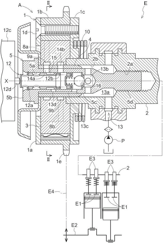
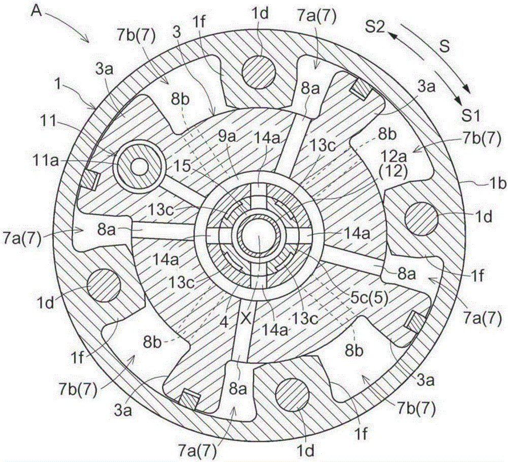
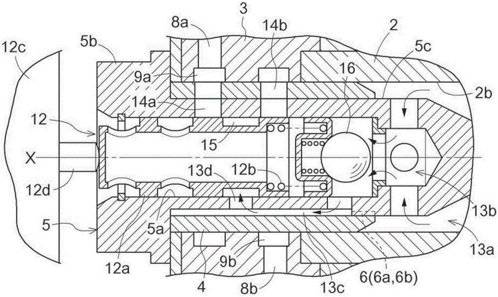
[0054] Figure 1 to Figure 6 A valve timing control device A according to the present embodiment is shown, which controls the opening and closing timing of the intake valve E1 in the engine E for an automobile.
[0055] Valve timing control device A such as figure 1 , figure 2 As shown, there is an aluminum alloy casing 1 that can rotate synchronously with the crankshaft E2 of the engine E, and is supported on the inside of the casing 1 so as to be rotatable on the same rotation axis X, and is connected to the intake valve for opening and closing. The inner rotor 3 made of aluminum alloy rotates integrally with the camshaft 2 .
[0056] Inside the inner rotor 3 are provided resin or aluminum alloy sleeves 4 and steel OCV bolts 5 for connecting the inner rotor 3 and the camshaft 2 .
[0057] The OCV bolt 5 passes through and is provided inside the sleeve 4, and is formed into a cylindrical shape including a cylindrical shaft portion 5c having an internal space 5a opened at ...
no. 2 approach
[0101] Figure 7 Shown is a valve timing control device A of the second embodiment.
[0102] The difference between the valve timing control device A of this embodiment and the first embodiment is that the introduction path 13c is provided on the outer peripheral surface of the cylindrical shaft portion 5c, and at the same time, the connection between the advance angle communication path 14a and the advance angle flow path 8a is advanced. The angled annular flow path 9 a and the retarded angle annular flow path 9 b communicating the retarded angle communication path 14 b with the retarded angle flow path 8 b are provided on the outer peripheral surface of the sleeve 4 .
[0103] The structure of other parts is the same as that of the first embodiment.
no. 3 approach
[0105] Figure 8 , Figure 9 Shown is a valve timing control device A of a third embodiment.
[0106] The difference between the valve timing control device A of this embodiment and the first embodiment is that the introduction path 13c is provided on the inner peripheral surface of the sleeve 4, and at the same time, the advance angle communication path 14a and the advance angle flow path 8a are advanced. The angular annular flow path 9 a and the retarded angle annular flow path 9 b connecting the retarded angle communication path 14 b and the retarded angle flow path 8 b are provided on the inner peripheral surface of the inner rotor 3 .
[0107] The structure of other parts is the same as that of the first embodiment.
PUM
 Abstract
Description
Claims
Application Information
 - R&D
- Intellectual Property
- Life Sciences
- Materials
- Tech Scout
- Unparalleled Data Quality
- Higher Quality Content
- 60% Fewer Hallucinations
Browse by: Latest US Patents, China's latest patents, Technical Efficacy Thesaurus, Application Domain, Technology Topic, Popular Technical Reports.
© 2025 PatSnap. All rights reserved.Legal|Privacy policy|Modern Slavery Act Transparency Statement|Sitemap|About US| Contact US: help@patsnap.com


