
Pipe laying machine device

A technology of pipe machine and casing, applied in the field of pipe laying machine device, can solve the problem of large-scale device and achieve the effect of simple connection

Active Publication Date: 2012-08-22
NIPPON SHARYO
View PDF4 Cites 0 Cited by
  • Summary
  • Abstract
  • Description
  • Claims
  • Application Information

AI Technical Summary

Problems solved by technology

Therefore, it is necessary to make the connecting rod 325 a strong member to increase the rigidity, and there is a problem of increasing the size of the device.

Method used


Image

  • Pipe laying machine device
  • Pipe laying machine device
  • Pipe laying machine device

Examples


Embodiment Construction

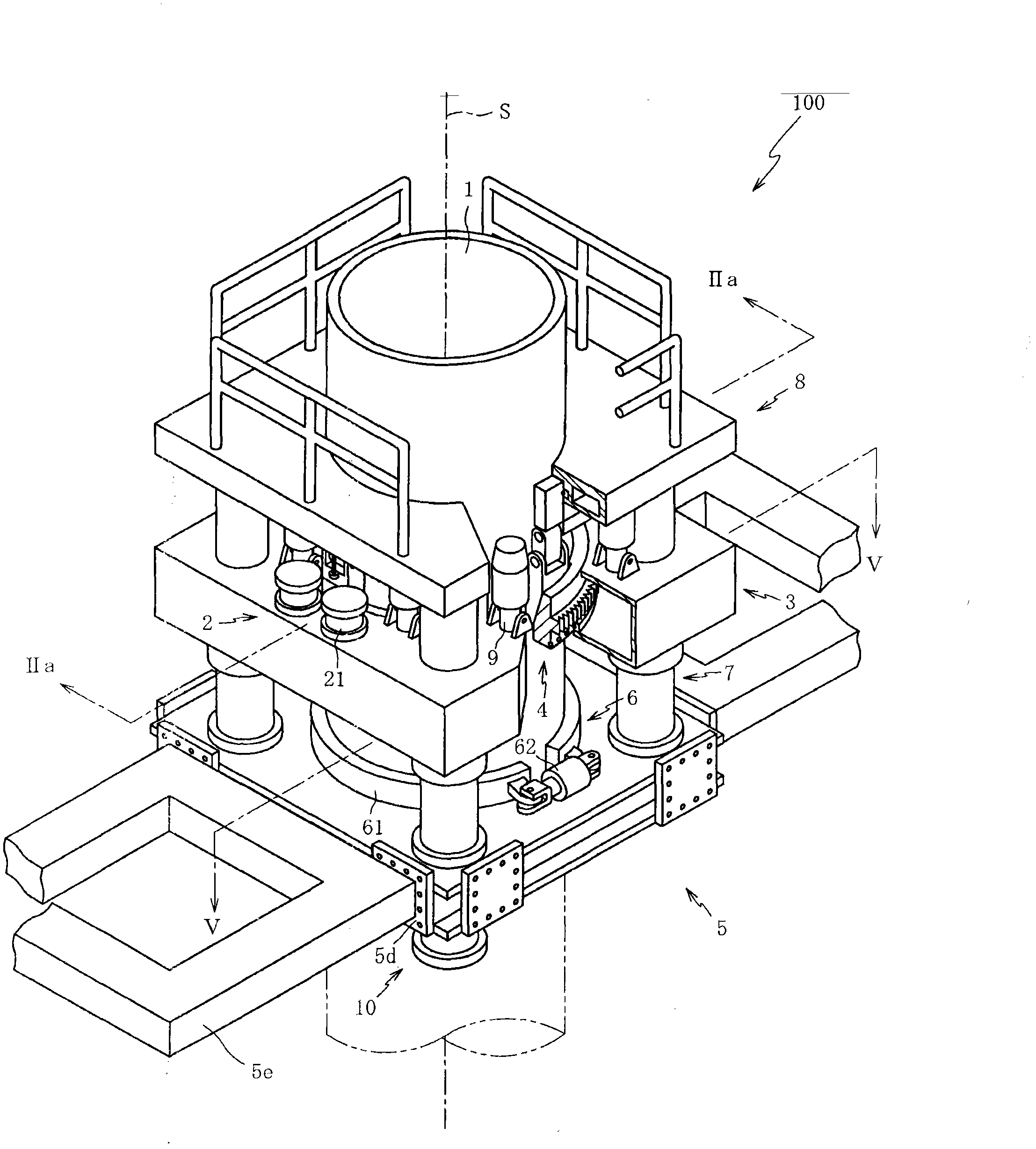
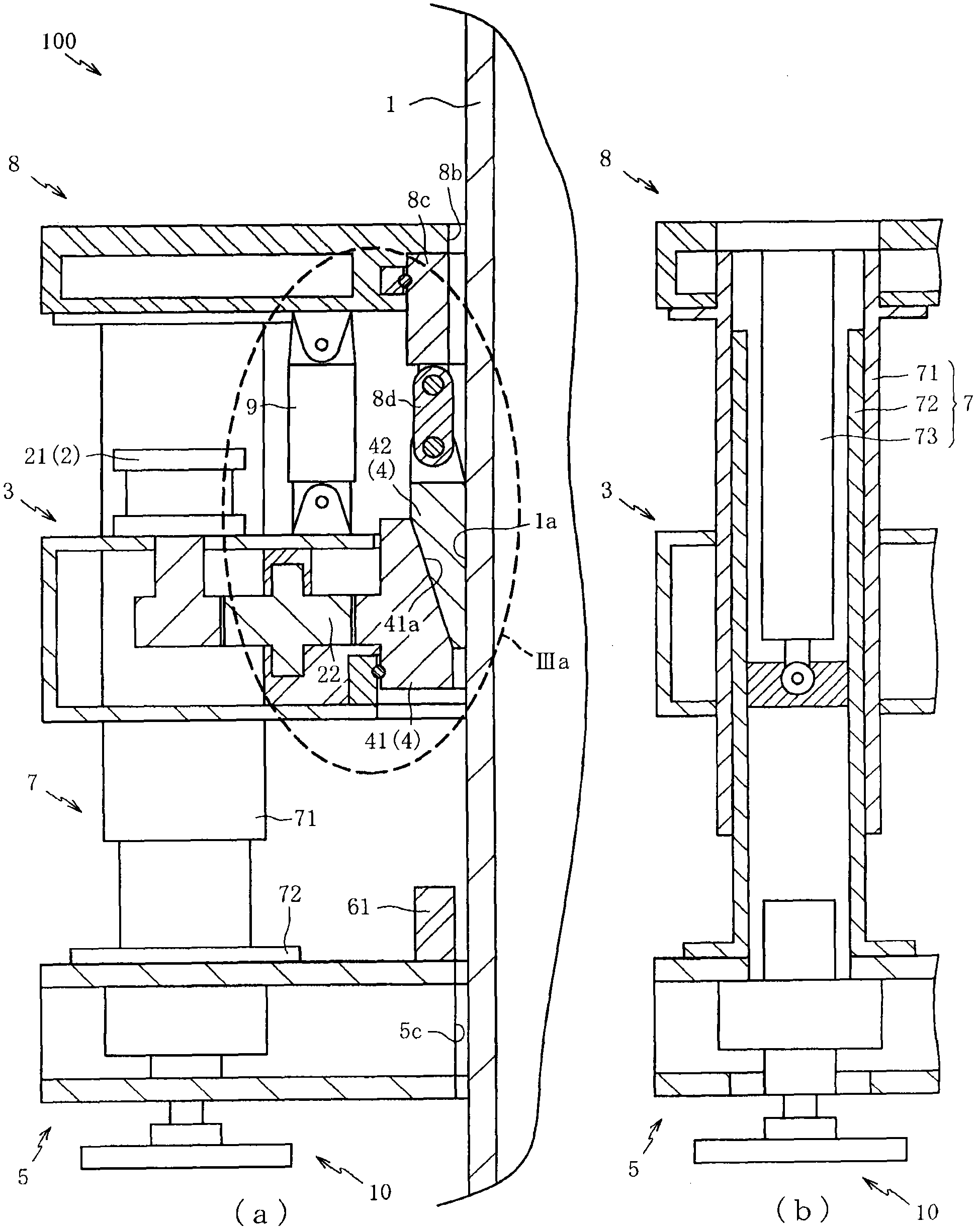
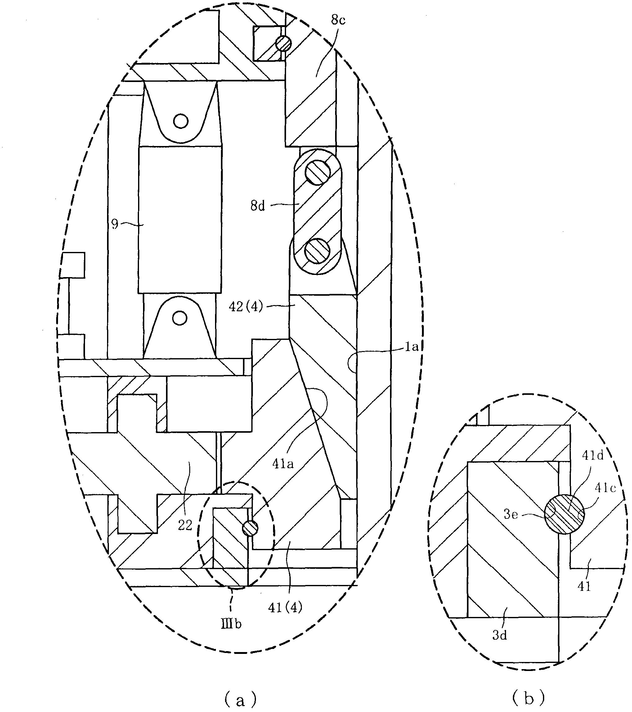
[0051] Hereinafter, preferred embodiments of the present invention will be described with reference to the drawings. First, refer to figure 1 and figure 2 The configuration of the pipe layer device 100 will be described. figure 1 It is a perspective view of the pipe layer device 100 according to one embodiment of the present invention, and is shown in a state where the elevating member 3 and part of the upper frame member 8 are cut. figure 2 (a) is an enlarged representation figure 1 An enlarged cross-sectional view of a portion of the pipelayer device 100 taken along line IIa-IIa, figure 2 (b) is a sectional view of the thrust jack 7 .

[0052] The pipe layer device 100 is a device for pile construction in which a vertical vertical hole is excavated by pressing the casing 1 against the ground while rotating it. figure 1 As shown, it mainly has: a rotating drive mechanism 2, a lifting part 3, a main clamping part 4, a lower frame part 5, an auxiliary clamping part ...


PUM


Abstract

The invention discloses a pipe laying machine device, which can be used for reducing noise and vibration generated during releasing of a bushing and realizing miniaturization. An upper frame component (8) provided with a clamping component (42) is connected with an elevating component (3) provided with a conical component (41) through a clamping pressure cylinder (9); the elevating component (3) descends relative to the upper frame component (8) in a state that the upper frame component (8) is fixed, and the bushing (1) is released, so that the bushing (1) can be released, the clamping component (42) which is pressed towards the bushing (1) is prevented from ascending, and the bushing (1) is prevented from rising; and moreover, rotating force from a rotary driving mechanism (2) is transmitted from the conical component (41) to the bushing (1), so that upsizing of a component caused by increase in the wall thickness for increasing the rigidity can be prevented. The result is that: noise and vibration generated during releasing of the bushing (1) can be reduced, and miniaturization is realized.

Description

[0001] This application is a divisional application of an invention patent application named "pipe laying machine device" with an application date of October 19, 2009 and application number 200910205301.7. technical field [0002] The present invention relates to a pipe layer device, in particular to a pipe layer device capable of reducing the generation of noise and vibration during casing release and achieving miniaturization. Background technique [0003] A pipelayer device is known as an apparatus for digging a hole for forming the pile inside in order to form a pile supporting a building underground. Here, refer to Figure 6 A conventional pipe layer device will be described. [0004] Figure 6 (a) and Figure 6 (b) is a cross-sectional view of a conventional pipe layer device 200 , 300 . Such as Figure 6 As shown in (a), the pipelayer device 200 has a plurality of thrust jacks 210 that support the elevating member 202 so as to be able to move up and down with respect...

Claims


Application Information

Patent Timeline
Patent Type & Authority Applications(China)
IPC IPC(8): E02F5/20
Inventor 岩仓明栗本真司
Owner NIPPON SHARYO
Learn More