
Internal combustion engine

A technology for internal combustion engines and valve trains, applied in mechanical equipment, engine components, machines/engines, etc., can solve the problems of cylinder block miniaturization, late oil return, and large oil capacity, so as to ensure air tightness and stagnant residual volume The effect of reducing and securing strength

Active Publication Date: 2020-10-09
HONDA MOTOR CO LTD
View PDF7 Cites 0 Cited by
  • Summary
  • Abstract
  • Description
  • Claims
  • Application Information

AI Technical Summary

Problems solved by technology

[0003] However, in the above-mentioned Japanese Patent Application Laid-Open No. 2007-002747, the oil return passage is provided separately from the camshaft transmission chain chamber. Therefore, it is necessary to provide a space for the return passage in the cylinder block, thereby making the cylinder block small. hindering factors
[0004] In addition, in the above-mentioned Japanese Patent Application Laid-Open No. 2007-002747, the camshaft transmission chain chamber itself is used as the oil return passage, so the size of the cylinder block becomes easy, and on the other hand, the return of oil tends to be delayed. , but it is necessary to make the oil capacity more in advance

Method used


Image

  • Internal combustion engine
  • Internal combustion engine
  • Internal combustion engine

Examples


Embodiment Construction

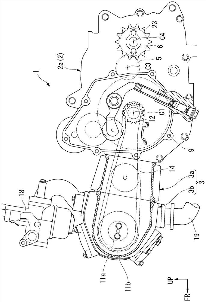
[0030] Hereinafter, embodiments of the present invention will be described with reference to the drawings. It should be noted that directions such as front, rear, left, and right in the following description are the same as the directions for the vehicle described below unless otherwise specified. In addition, arrows FR indicating the front of the vehicle, arrows LH indicating the left of the vehicle, and arrows UP indicating the upward direction of the vehicle are shown at appropriate locations in the drawings used in the following description.

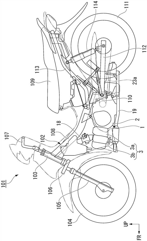
[0031] exist figure 1 In the illustrated motorcycle (straddle type vehicle) 101 , the frame 102 is integrally formed by joining various steel materials by welding or the like. The frame 102 has a single main pipe 108 extending rearward and downward from the head pipe 103 that supports the front wheel suspension system in a steerable manner, and the space between the head pipe 103 and the seat 109 for the occupant is set as a lower p...


PUM


Abstract

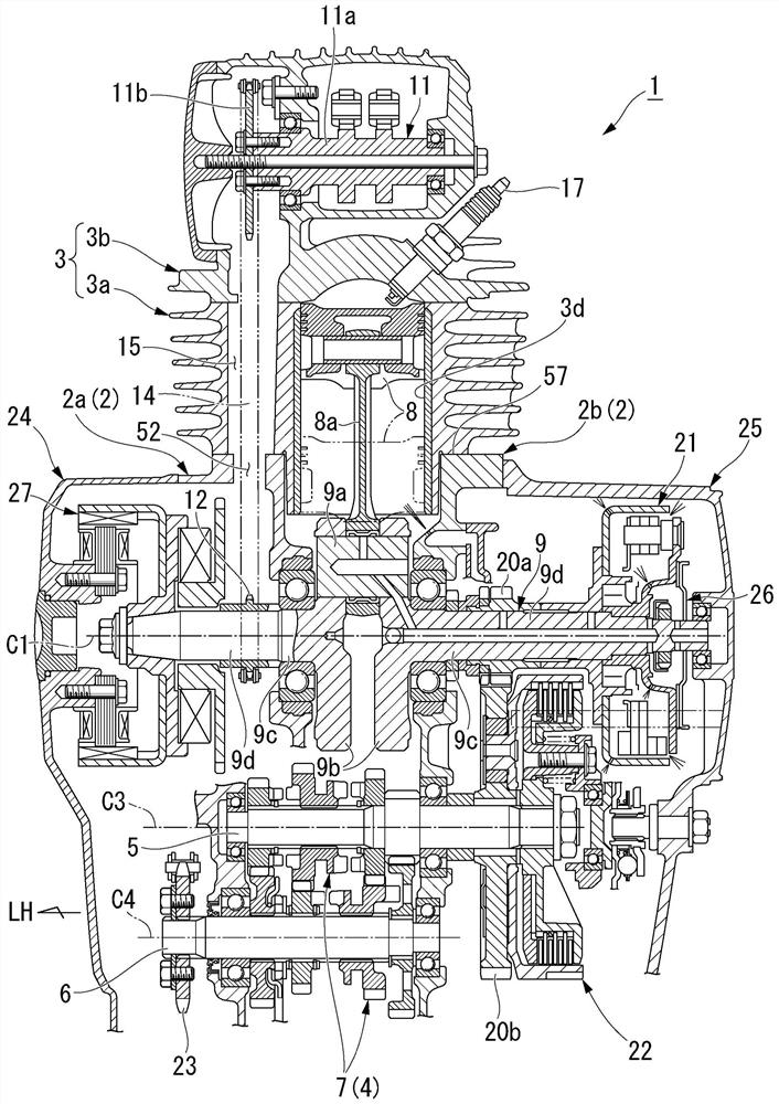
The purpose of the present invention is to achieve an internal combustion engine in which a cylinder block is reduced in size and oil returns smoothly. The internal combustion engine comprises a camshaft transmission chain chamber. The cam shaft transmission chain chamber is formed in the air cylinder body and contains a cam shaft transmission chain and functions as a return passage for returningthe oil supplied into the cylinder head into the crankcase (2). The crankcase (2) is provided with an oil storage part (51) on the bottom surface side, the crankcase (2) is provided with a crankcase side camshaft transmission chain chamber (52) connected with the camshaft transmission chain chamber, and an oil falling hole (54) communicated with the oil storage part (51) is formed in the bottom wall (53) of the crankcase side camshaft transmission chain chamber (52).

Description

technical field [0001] The present invention relates to internal combustion engines. Background technique [0002] Conventionally, as a structure for returning the oil supplied to the valve chamber of the cylinder head to the oil chamber of the crankcase, for example, as disclosed in Japanese Patent Application Laid-Open No. 2007-002747, there is an oil return valve provided separately from the camshaft transmission chain chamber. The structure of the pathway. In addition, as disclosed in Japanese Patent Application Laid-Open No. 2004-218507, there is a configuration in which the camshaft chain chamber itself is used as an oil return passage. [0003] However, in the above-mentioned Japanese Patent Application Laid-Open No. 2007-002747, the oil return passage is provided separately from the camshaft transmission chain chamber. Therefore, it is necessary to provide a space for the return passage in the cylinder block, thereby making the cylinder block small. hindering facto...

Claims


Application Information

Patent Timeline
Patent Type & Authority Applications(China)
IPC IPC(8): F01M11/00F01M11/03F01M9/10
CPCF01M11/0004F01M11/03F01M9/10F01M2011/0029
Inventor 原田诚上村拓真北田芳宏铃木达阳
Owner HONDA MOTOR CO LTD
Learn More