
Corner combining machine having accurate clamping function and used for aluminum alloy machining

A technology of aluminum alloy and angle forming machine, which is applied in metal processing equipment, manufacturing tools, feeding devices, etc., can solve the problems of deviation of joints, time-consuming and laborious, and inclination of aluminum alloy parts.

Active Publication Date: 2021-04-20
广东杨达鑫科技有限公司
View PDF6 Cites 0 Cited by
  • Summary
  • Abstract
  • Description
  • Claims
  • Application Information

AI Technical Summary

Problems solved by technology

[0005] Aiming at the deficiencies of the prior art, the present invention provides a corner forming machine with precise clamping function for aluminum alloy processing, capable of automatically sending the aluminum alloy parts into the stopper smoothly and avoiding the connection of the aluminum alloy parts during the corner forming process. The advantage of the deviation occurs at the position, which solves the need for people to hold the aluminum alloy parts and send them to the stopper. This method is not only time-consuming and laborious, but also causes the aluminum alloy parts to tilt when the aluminum alloy parts are long, thereby reducing the assembly time. In addition, when the heights of the two end faces of the aluminum alloy parts are inconsistent, it is easy to cause deviations at the joints of the two aluminum alloy parts when the corners are assembled, resulting in the scrapping of the product

Method used


Image

  • Corner combining machine having accurate clamping function and used for aluminum alloy machining
  • Corner combining machine having accurate clamping function and used for aluminum alloy machining
  • Corner combining machine having accurate clamping function and used for aluminum alloy machining

Examples


Embodiment Construction

[0026] The following will clearly and completely describe the technical solutions in the embodiments of the present invention with reference to the accompanying drawings in the embodiments of the present invention. Obviously, the described embodiments are only some, not all, embodiments of the present invention. Based on the embodiments of the present invention, all other embodiments obtained by persons of ordinary skill in the art without making creative efforts belong to the protection scope of the present invention.

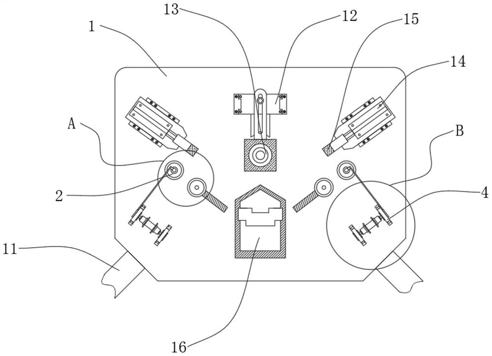
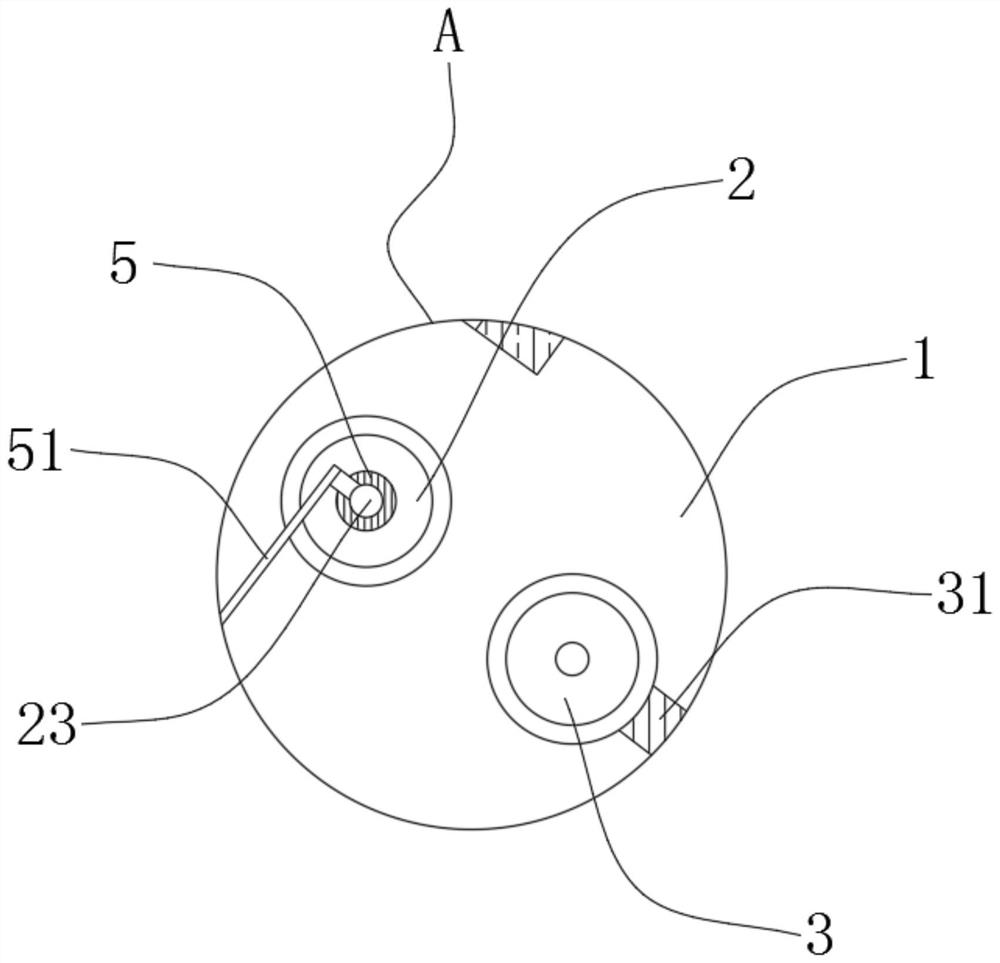
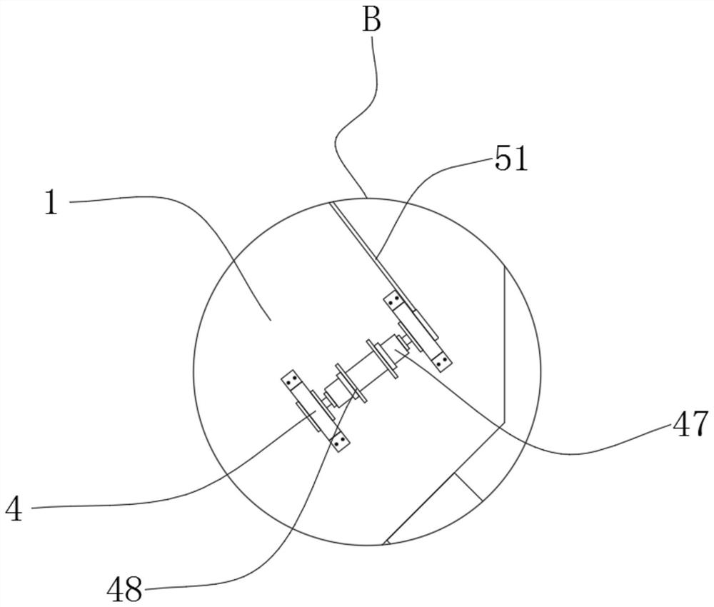
[0027] see Figure 1-7 , a corner forming machine with precise clamping function for aluminum alloy processing, comprising a workbench 1, one side of the workbench 1 is fixedly connected with a placement plate 11, the top of the workbench 1 is fixedly connected with a support frame 12, and the support frame 12 The top of the workbench 1 is fixedly connected with a lower pressure part 13, and the top of the workbench 1 is located on both sides of the lower pres...


PUM


Abstract

The invention relates to the technical field of aluminum alloy machining equipment, and discloses a corner combining machine having an accurate clamping function and used for aluminum alloy machining. The machine comprises a workbench, the top of the workbench is fixedly connected with a driving wheel, the inner side wall of the driving wheel is fixedly connected with an inner gear, the inner side wall of the inner gear is engaged with outer transmission teeth, the inner side walls of the outer transmission teeth are fixedly connected with transmission rods, and the side, close to the driving wheel, of the top of the workbench is glidingly connected with a driven wheel. The transmission rods are fixedly connected to the inner side walls of the outer transmission teeth, the driven wheel is glidingly connected to the side, close to the driving wheel, of the top of the workbench, a supporting seat is fixedly connected to the top of the workbench, an inner supporting frame is fixedly connected to the interior of the supporting seat, sliding rails are symmetrically distributed on the left side and the right side of the inner side wall of the inner supporting frame, the upper side and the lower side of the inner side wall of the inner supporting frame are fixedly connected with adjusting springs, and one end of each adjusting spring is fixedly connected with a roller base.

Description

technical field [0001] The invention relates to the technical field of aluminum alloy processing equipment, in particular to an angle forming machine with precise clamping function for aluminum alloy processing. Background technique [0002] In the processing equipment of aluminum alloy, the processing of aluminum alloy doors and windows usually adopts corner forming machine, which is a special equipment for the production of high-grade broken bridge aluminum alloy doors and windows, and is suitable for 90-degree angle connection of corner-coded aluminum doors and windows. In some areas, it is also called corner squeezer, corner bumper, and corner corner machine. According to the different angles that can be assembled, it is divided into single-head angle machine, double-head angle machine, and four-head angle machine. At present, the single-head angle machine is more common. [0003] In the prior art, in the process of forming corners, it is necessary for a person to hold ...

Claims


Application Information

Patent Timeline
IPC IPC(8): B21D43/02B21D43/08B21D39/00
Inventor 陈露
Owner 广东杨达鑫科技有限公司
Learn More