
Metal plate intelligent polishing device

A technology of metal plate and polishing device, which is applied in the direction of grinding drive device, metal processing equipment, grinding/polishing equipment, etc., and can solve the problems of unstable hydraulic pressure of the polishing wheel and poor polishing flatness of the surface of the metal plate, etc.

Inactive Publication Date: 2021-04-20
OKUMTEC TECH WENZHOU CO LTD
View PDF8 Cites 0 Cited by
  • Summary
  • Abstract
  • Description
  • Claims
  • Application Information

AI Technical Summary

Problems solved by technology

[0004] The purpose of the present invention is to solve the problem of hydraulic instability in the process of polishing wheel in the prior art, which leads to poor polishing flatness of the surface of the metal plate, and proposes an intelligent polishing device for metal plates

Method used


Image

  • Metal plate intelligent polishing device
  • Metal plate intelligent polishing device
  • Metal plate intelligent polishing device

Examples


Embodiment 1

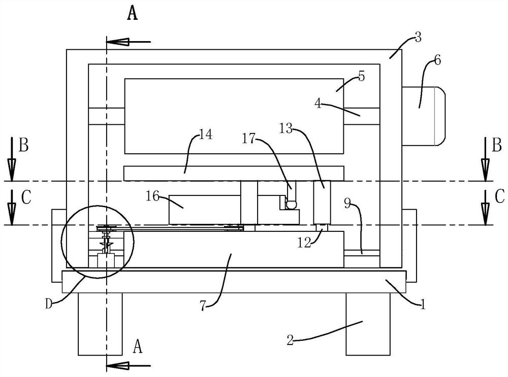
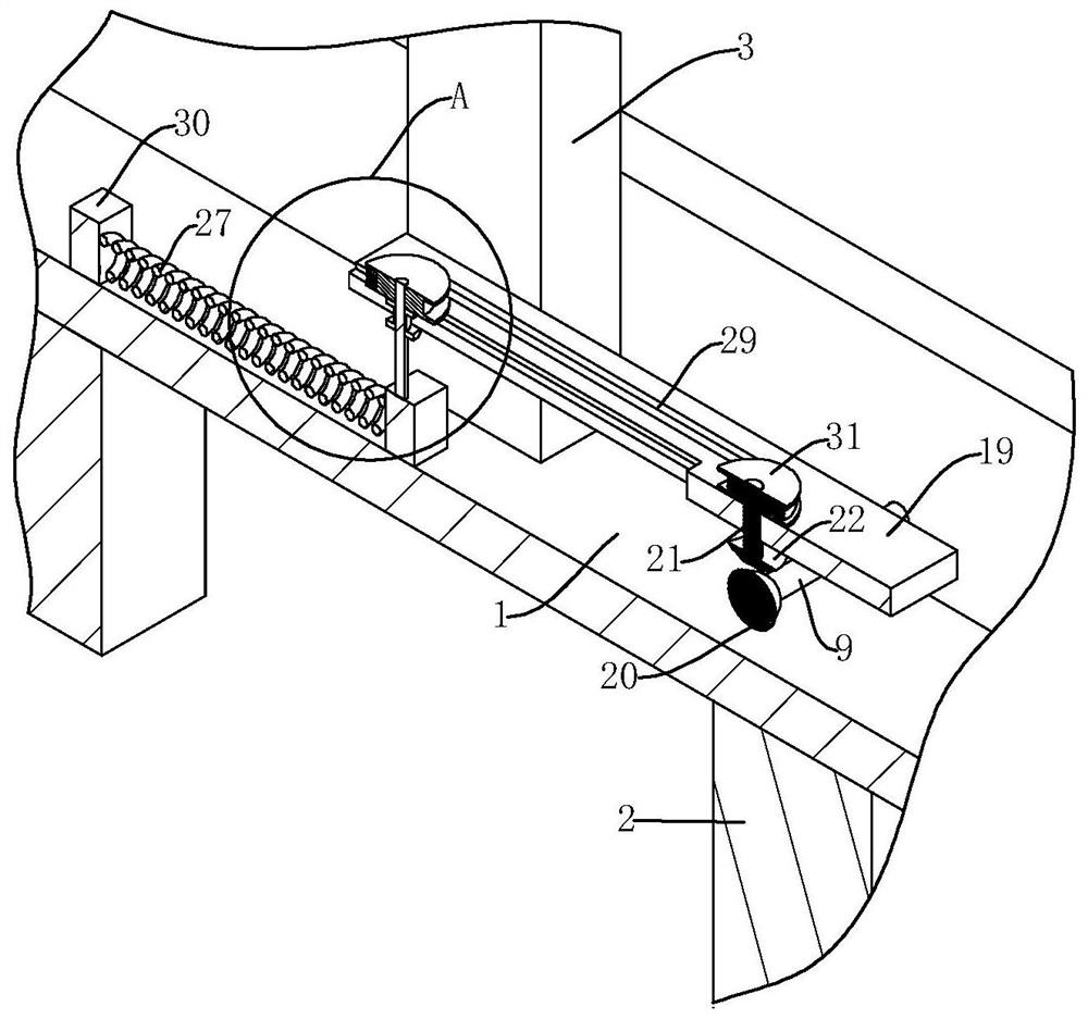
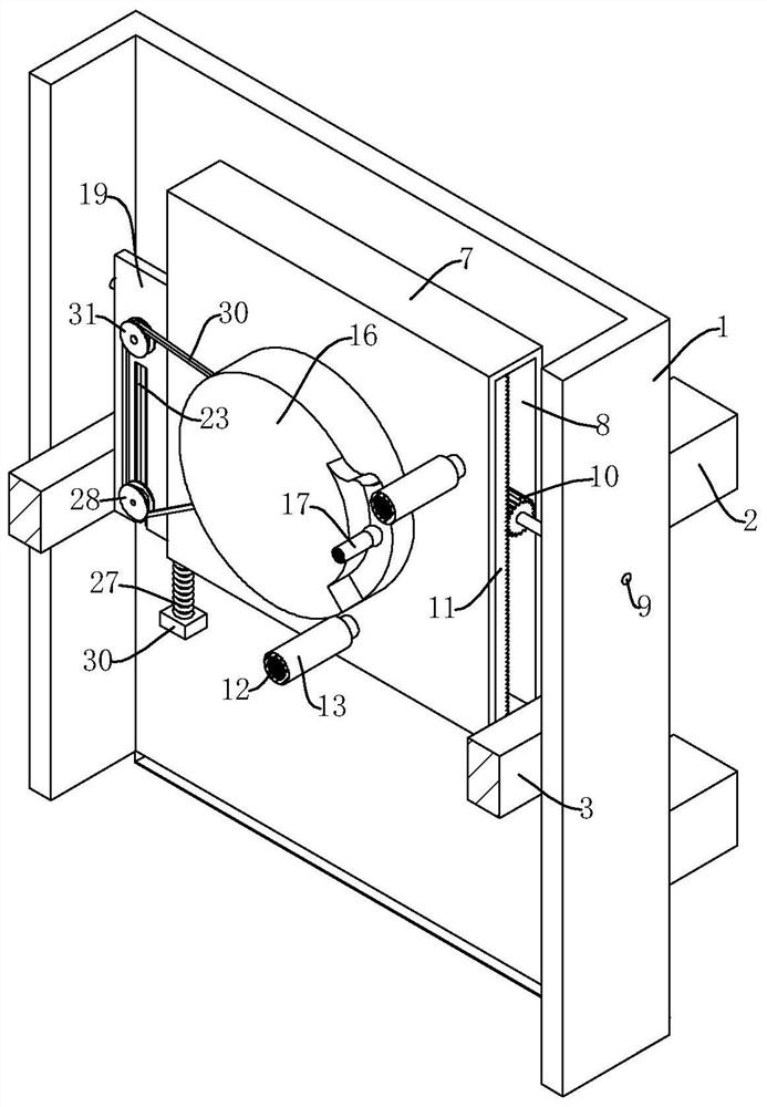
[0024] refer to Figure 1-6 , an intelligent polishing device for metal plates, comprising a base 1, four support columns 2 are evenly and fixedly installed on the bottom of the base 1, a U-shaped frame 3 is fixedly installed in the middle of the top of the base 1, and a rotating shaft 4 is installed on the inner side of the U-shaped frame 3 through bearings, Grinding roller 5 is fixedly installed on the shaft 4 in the U-shaped frame 3, and a motor 6 is fixedly installed on the outside of the U-shaped frame. A groove 8 is provided, and a rotating rod 9 is placed on one side of the base 1. The rotating rod 9 runs through the base 1 and the groove 8 and is installed on the base 1 through bearings (the two ends of the rotating rod 9 are installed on the base 1 through bearings, and the rotating rod 9 9 completely penetrates through the groove 8), a gear 10 is fixedly installed on the rotating rod 9 inside the groove 8, and a rack 11 is installed in the groove 8 through a bolt, an...

Embodiment 3

[0028] refer to Figure 1-6 , the adjustment mechanism includes a chute 23 set on the fixed plate 19, a fixed block 30 installed on the base 1, a slider 24 is slidably arranged in the chute 23, a cylinder 25 is placed on the slider 24, and the cylinder 25 runs through the slider 24 and connecting block 26 is installed by bearing, and spring 27 is installed between connecting block 26 and fixed block 30, and the third pulley 28 is installed on the column 25 at the top of slide block 24 by bearing, first pulley 18, second pulley 31 , A belt 29 is installed between the third pulley 28, clearance fit between the slide block 24 and the chute 23, and the spring 27 is carbon spring steel. By setting the clearance fit between the slider 24 and the slide groove 23 , the movement of the third pulley 28 is more stable, thereby indirectly increasing the service life of the slider 23 . By setting the spring 27 as carbon spring steel, the service life of the spring 27 is increased, and the...


PUM


Abstract

The invention relates to the technical field of polishing equipment, in particular to a metal plate intelligent polishing device. The device comprises a base, wherein four supporting columns are evenly mounted at the bottom of the base, a U-shaped frame is mounted in the middle of the top of the base, a rotating shaft is mounted at the inner side of the U-shaped frame through a bearing, a grinding roller is mounted on the rotating shaft in the U-shaped frame, a motor is mounted at the outer side of the U-shaped frame, an output shaft of the motor is connected with the rotating shaft, a moving plate is placed at the top of the base, a groove is formed in the moving plate, two supporting rods are mounted at the top of the moving plate, the two supporting rods are arranged in a spaced mode, the top of each supporting rod is sleeved with a sleeve rod in a sliding mode, a carrying plate is mounted between the tops of the two sleeve rods, a short rod is mounted in the middle of the top of the moving plate through a bearing, a rotary disc is mounted at the top of the short rod, a sliding rod is mounted at on one side of the bottom of the carrying plate, one end of the sliding rod abuts against the rotary disc, and the short rod is connected with a rotating rod through a transmission mechanism. The device has very high practical value and is worth popularizing.

Description

technical field [0001] The invention relates to the technical field of polishing equipment, in particular to an intelligent polishing device for metal plates. Background technique [0002] Polishing refers to the use of mechanical, chemical or electrochemical action to reduce the surface roughness of the workpiece to obtain a bright and smooth surface. It is a modification process on the surface of the workpiece using polishing tools and abrasive particles or other polishing media, and metal plates often need to be polished. The traditional polishing method is that the operator uses a hand-held polishing device to polish, which not only has low efficiency, but also has poor flatness, which affects the polishing process. [0003] Most of the polishing machines in the prior art use the polishing wheel to move to polish the metal plate, but the phenomenon of hydraulic instability often occurs during the movement of the polishing wheel, which leads to poor polishing flatness on...

Claims


Application Information

Patent Timeline
Patent Type & Authority Applications(China)
IPC IPC(8): B24B29/02B24B41/06B24B41/02B24B47/12B24B47/22
Inventor 徐泷包仲南李代明马德高李卫东
Owner OKUMTEC TECH WENZHOU CO LTD
Learn More