Cylinder type clamp

A fixture and barrel technology, which is applied in the direction of grinding workpiece supports, etc., can solve problems such as easy deformation of parts

Active Publication Date: 2021-04-20
ACCU JIANGSU CO LTD
View PDF7 Cites 0 Cited by
  • Summary
  • Abstract
  • Description
  • Claims
  • Application Information

AI Technical Summary

Problems solved by technology

In the prior art, the left and right jaws are generally used to clamp rod parts, and t

Method used


Image

  • Cylinder type clamp
  • Cylinder type clamp
  • Cylinder type clamp

Examples


Embodiment Construction

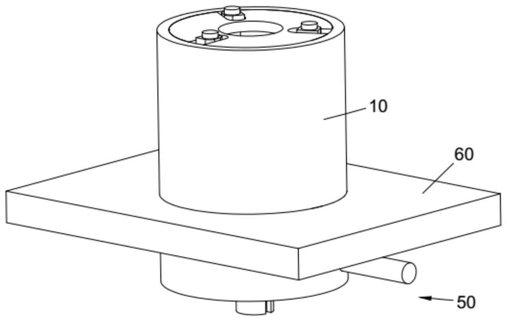
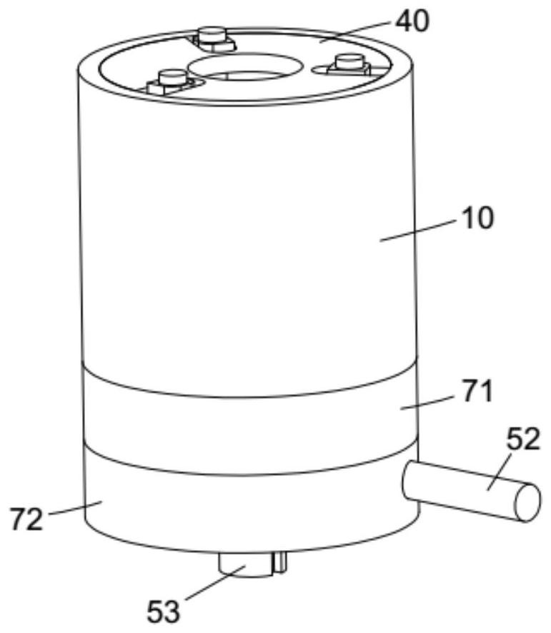
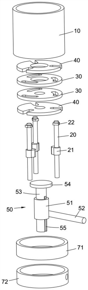
[0024] combine Figure 1 to Figure 4 , a barrel clamp, including a barrel 10, a rod 20, a track plate 30, a guide plate 40, and a rotating device 50.

[0025] The cylinder 10 is fixed on the workbench 60, the track disk is fixed in the cylinder, the guide disk is pivotally connected in the cylinder, and the guide disk is connected with the rotating device; Figure 7 As shown, the head end 32 of any arc-shaped groove is closer to the center of the track disc than the tail end 33, and the guide disc is provided with some radial guide grooves 41, such as Figure 8 As shown, a number of guide grooves and a number of arc-shaped grooves are set up and down correspondingly in a one-to-one manner, and a rod 20 is inserted in each arc-shaped groove, the rod passes through the guide groove, and a clamping block 21 is provided on the rod.

[0026] Rod parts extend into the barrel 10, manually drive the rotating device 50, the rotating device drives the guide disc 40 to rotate, the guide...


PUM


Abstract

The invention discloses a cylinder type clamp. The cylinder type clamp comprises a cylinder, rods, a track disc, a guide disc and a rotating device, wherein the cylinder is fixed on a workbench; the track disc is fixed in the cylinder, the guide disc is pivoted in the cylinder, and the guide disc is connected with the rotating device; the track disc is provided with a plurality of arc-shaped grooves evenly distributed in the circumferential direction of the track disc, and the head end of any arc-shaped groove is closer to the center of the track disc than the tail end of the corresponding arc-shaped groove; the guide disc is provided with a plurality of radial guide grooves, and the plurality of guide grooves and the plurality of arc-shaped grooves are arranged up and down in a one-to-one correspondence mode; and one rod is inserted into each arc-shaped groove and penetrates through the corresponding guide groove, and clamping blocks are arranged on the rods. A rod part extends into the cylinder, the rotating device drives the guide disc to rotate, the guide disc drives the rods in the guide grooves, the rods move along the arc-shaped grooves of the track disc, the clamping blocks on the rods tend to surround the rod part and finally clamp the rod part, and the rod part is clamped in the center of the cylinder; and the part can be evenly stressed, stably clamped and not prone to local deformation.

Description

technical field [0001] The invention relates to a clamp for automobile parts. Background technique [0002] Rod parts, such as connecting rods on automobiles, need to be ground during processing or repairing to meet the precise size requirements. At the same time, grinding can also repair the surface defects of the parts. Grinding tools This could be a file or sandpaper. While workers are surface-treating rod parts with tools, the parts need to be positioned on the workbench. In the prior art, the left and right jaws are generally used to clamp the rod parts, and the parts are easily deformed due to the force on the left and right sides of the parts. Contents of the invention [0003] The technical problem to be solved by the invention is: how to position the rod parts on the workbench evenly under force. [0004] In order to solve the above technical problems, the present invention provides the following technical solutions: a cylindrical clamp, including a cylinder, a...

Claims


Application Information

Patent Timeline
IPC IPC(8): B24B41/06
Inventor 尤丹雷
Owner ACCU JIANGSU CO LTD
Why Eureka
Try Eureka