

Injection mold for photoelectric switch shell
An injection mold and photoelectric switch technology, applied in the field of plastic injection molds, can solve the problems of uneven quality mixing and multiple air lines on the surface of the photoelectric switch housing, and achieve good exhaust effect.
- Summary
- Abstract
- Description
- Claims
- Application Information
AI Technical Summary
Problems solved by technology
Method used
Image

Examples
no. 1 example
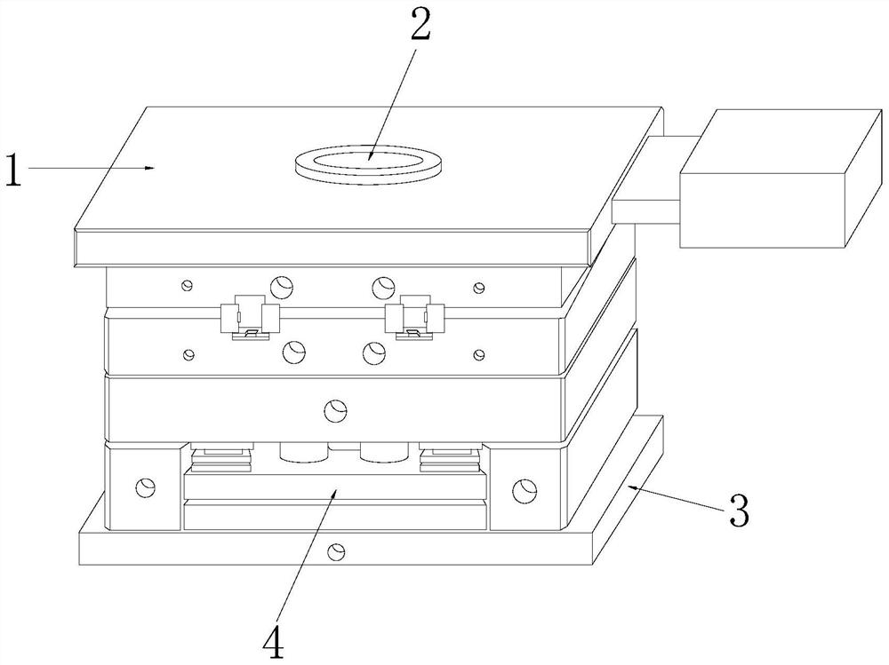
[0028] Such as Figure 1-Figure 4 As shown, the present invention provides a technical scheme of an injection mold for a photoelectric switch housing:
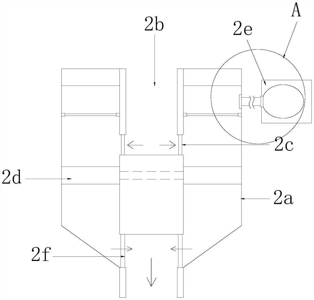
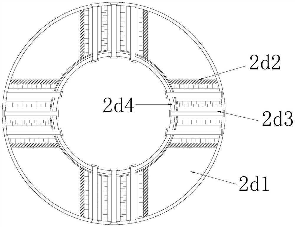
[0029] Such as Figure 1-Figure 2 As shown, a photoelectric switch housing injection mold, its structure includes an upper mold 1, a plastic guiding device 2, a lower mold 3, and a release plate 4, and the plastic guiding device 2 is located in the middle of the upper mold 1 and connected by electric welding, The lower mold 3 is arranged under the upper mold 1 and fits together, the stripping plate 4 is arranged on the upper surface of the lower mold 3 and connected by electric welding, and the plastic guiding device 2 includes a cavity 2a, an injection hole 2b, an upper The overflow ring 2c, the squeeze mechanism 2d, the degassing structure 2e, and the lower overflow ring 2f, the injection hole 2b is set in the middle of the cavity 2a and is an integrated structure, and the overflow ring 2c is set in the injection hole 2b T...
no. 2 example
[0038] Such as figure 1 , figure 2 , Figure 5 As shown, the present invention provides a technical scheme of an injection mold for a photoelectric switch housing:
[0039] Such as Figure 1-Figure 2As shown, a photoelectric switch housing injection mold, its structure includes an upper mold 1, a plastic guiding device 2, a lower mold 3, and a release plate 4, and the plastic guiding device 2 is located in the middle of the upper mold 1 and connected by electric welding, The lower mold 3 is arranged under the upper mold 1 and fits together, the stripping plate 4 is arranged on the upper surface of the lower mold 3 and connected by electric welding, and the plastic guiding device 2 includes a cavity 2a, an injection hole 2b, an upper The overflow ring 2c, the squeeze mechanism 2d, the degassing structure 2e, and the lower overflow ring 2f, the injection hole 2b is set in the middle of the cavity 2a and is an integrated structure, and the overflow ring 2c is set in the inje...
PUM
 Abstract
Description
Claims
Application Information