
Vehicle malfunction cause identifying device

A technology for determining the cause of a failure and a device, which is applied in the directions of registration/indication of vehicle operation, machine learning, registration/indication, etc., can solve the problems of determining the cause of the failure and the decrease in accuracy of determining the cause of the failure, and achieve the effect of improving accuracy

Pending Publication Date: 2021-04-20
TOYOTA JIDOSHA KK
View PDF1 Cites 0 Cited by
  • Summary
  • Abstract
  • Description
  • Claims
  • Application Information

AI Technical Summary

Problems solved by technology

[0003] Furthermore, depending on the fault, it may be difficult to identify the cause of the fault from the detected values ​​of the on-board sensors mounted on the vehicle.
In other words, when the sensor that detects the operating state at the time of the failure, which is easy to identify the cause of the failure, is not mounted on the vehicle, the on-board sensor that detects the operating state at the time of the failure, which is difficult to identify the cause of the failure In the detection value of , the accuracy of determining the cause of the failure may decrease

Method used


Image

  • Vehicle malfunction cause identifying device
  • Vehicle malfunction cause identifying device
  • Vehicle malfunction cause identifying device

Examples


Embodiment Construction

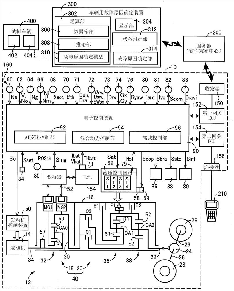
[0035] In an embodiment of the present invention, the vehicle includes a power source and a power transmission device. The power transmission device includes the vehicle transmission. The gear ratio in this vehicle transmission is "rotational speed of the input-side rotating element / rotational speed of the output-side rotating element". The high speed side of the gear ratio is the high vehicle speed side on which the gear ratio becomes smaller. The low speed side in the gear ratio is the low vehicle speed side on which the gear ratio becomes larger. For example, the lowest gear-side gear ratio is a gear ratio on the lowest vehicle speed side on the lowest vehicle speed side, and is a maximum gear ratio at which the gear ratio becomes a maximum value.

[0036] In addition, the power source is, for example, an engine such as a gasoline engine or a diesel engine that generates power by burning fuel. In addition, as the power source, the vehicle may include an electric motor or...


PUM


Abstract

Disclosed is a vehicle malfunction cause identifying device. A cause for a malfunction in a vehicle is identified using a preset malfunction cause identifying model indicating a relation between the cause for the malfunction identified based on a detection value of an experimental vehicle sensor such as an oil pressure sensor, which is a detection value allowing the cause for the malfunction to be identified more easily than a detection value of an in-vehicle sensor group that is the same as an in-vehicle sensor group equipped in the vehicle, and the detection value of the in-vehicle sensor group, and the detection value of the in-vehicle sensor group when the malfunction has occurred in the vehicle. Therefore, in the case where the vehicle is not equipped with the experimental vehicle sensor, it is possible to improve the accuracy of the identification of the cause for the malfunction in the vehicle.

Description

technical field [0001] The present invention relates to a failure cause determination device for a vehicle that determines the cause of a failure occurring in a vehicle. Background technique [0002] There is known a failure cause identification device for a vehicle that, when a failure occurs in a vehicle, uses detection values ​​of an on-vehicle sensor mounted on the vehicle to detect the operating state of the vehicle to identify the cause of the failure. For example, the failure analysis system described in Japanese Patent Application Laid-Open No. 2006-27391 is exactly the same. In this Japanese Patent Application Laid-Open No. 2006-27391, it is disclosed that the correlation between vehicle state information that can be obtained from sensors mounted on the vehicle and surrounding environment information of the vehicle that can be obtained from an external mechanism outside the vehicle is formed into a database, and the It is used for fault analysis of vehicles. [00...

Claims


Application Information

Patent Timeline
Patent Type & Authority Applications(China)
IPC IPC(8): B60W50/02
CPCG07C5/0808G06N3/08G07C5/0816G06N20/00
Inventor 宫坂贤治田端淳北畑刚奥田弘一
Owner TOYOTA JIDOSHA KK
Learn More