Supercharge Your Innovation With Domain-Expert AI Agents!

Take-up device and electric hair drier thereof

A technology of a wire take-up device and a take-up reel, which is used in hair drying devices, devices for washing hair or scalp, clothing, etc. problem, to achieve the effect of uniform winding and good power-on effect

Pending Publication Date: 2021-04-20
慈溪市金悦电子有限公司
View PDF5 Cites 0 Cited by
  • Summary
  • Abstract
  • Description
  • Claims
  • Application Information

AI Technical Summary

Problems solved by technology

[0004] However, in the actual use process, the winding of the power cord is usually realized by the way of torsion spring winding, so the inventor found that the winding speed of the power cord often occurs too fast in the process of winding the power cord, and then the power cord occurs " Tail flicking phenomenon, causing the power cord to injure the user

Method used


Image

  • Take-up device and electric hair drier thereof
  • Take-up device and electric hair drier thereof
  • Take-up device and electric hair drier thereof

Examples


Embodiment 1

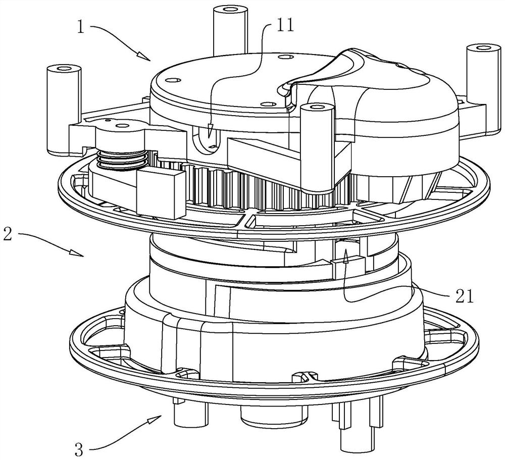
[0052] Embodiment 1 of the present application discloses a wire take-up device. refer to figure 1 The take-up device includes a slow gear box 1, a winding reel 2 and a limit cover 3 arranged in sequence in the axial direction, and the take-up reel 2 is rotatably connected between the slow gear box 1 and the limit cover 3 for winding power cable. Wherein, the winding reel 2 is provided with a wiring cavity, and the side wall of the winding reel 2 is provided with a wiring opening 21 communicating with the wiring cavity. One end of the power cord is inserted into the wiring cavity through the wiring opening 21, and the slow gear The outer periphery of the box 1 is provided with two lead holes 11 for connecting wires.

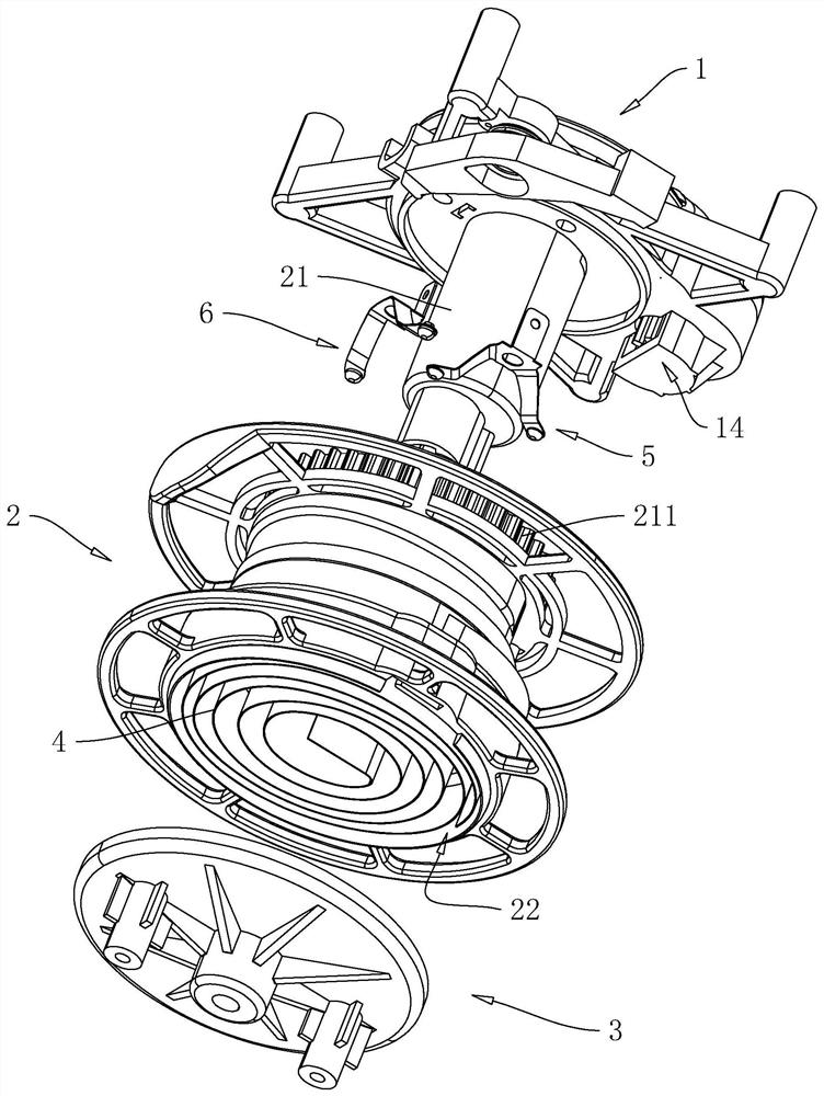
[0053] refer to figure 2 , The slow gear box 1 is provided with a central shaft 12 , the central shaft 12 axially penetrates the winding reel 2 and is fixedly connected with the limit cover 3 . The side of the reel 2 facing the limit cover 3 is provided with ...

Embodiment 2

[0085] Embodiment 2 of the present application discloses a hair dryer, referring to Figure 14 The hair dryer includes a front case 101 and a rear case 102 fixed to each other. Both the front case 101 and the rear case 102 are provided with a grip part 103, and the two grip parts 103 are spliced ​​together to form a grip for the hand to hold. Hold the handle. Between the front housing 101 and the rear housing 102, a heating module 104, a fan module 105, and a wire take-up device 106 are sequentially arranged. hair dryer. The heating module 104 and the fan module 105 are relatively fixed, the limit cover 3 of the wire take-up device 106 is fixed on the rear casing 102 , and the slow gear box 1 of the wire take-up device 106 is fixed on the casing of the fan module 105 . The electric wires are led out through the lead hole 11 on the slow gear box 1 and connected to the motor of the fan module 105 and the heating wire of the heating module 104 respectively.


PUM


Abstract

The invention relates to a take-up device. The take-up device comprises a retarding gear box, a winding reel and a limiting cover which are sequentially arranged in the axial direction, a center shaft is arranged on the retarding gear box in the axial direction, the center shaft axially penetrates through the winding reel and is fixedly connected with the limiting cover, and a containing cavity is formed in the side, facing the limiting cover, of the winding reel. A coil spring is arranged in the containing cavity, one end of the coil spring is fixedly connected with the center shaft, the other end of the coil spring is fixedly connected with the winding reel, and a speed reducing mechanism in linkage with the winding reel is arranged in the retarding gear box. The speed reducing mechanism is composed of a transmission gear set and a speed reducing gear set, the transmission gear set is in linkage with the winding reel, the speed reducing gear set is composed of at least one speed reducing gear piece, and each speed reducing gear piece comprises a speed reducing gear in linkage with the transmission gear set and a rotating shaft which is coaxially arranged and used for supporting the speed reducing gear in a rotating mode. The two ends of each rotating shaft are installed in the retarding gear box. The effect that a power line can be wound at a constant speed is achieved.

Description

technical field [0001] The present application relates to the field of household appliances, in particular to a wire take-up device and a hair dryer thereof. Background technique [0002] The hair dryer is a combination of a set of heating wires and a high-speed small fan. When energized, the heating wire will generate heat, and the wind blown by the fan will become hot air after passing through the heating wire. The hair dryer is mainly used for drying and shaping of hair, but it can also be used for local drying, heating and physical therapy in laboratories, physiotherapy rooms, industrial production, and art. [0003] Today's hair dryers usually use an external power cord to supply power to the fan and the heating wire, but this kind of hair dryer with an external power cord needs to wind the power cord on the handle or on the handle when storing the wires. On the housing of the hair dryer for storage. Another commonly used way to rewind the power cord is to build a ro...

Claims


Application Information

Patent Timeline
Patent Type & Authority Applications(China)
IPC IPC(8): B65H75/44B65H75/48A45D20/00
Inventor 金建军
Owner 慈溪市金悦电子有限公司
Features
  • R&D
  • Intellectual Property
  • Life Sciences
  • Materials
  • Tech Scout
  • Unparalleled Data Quality
  • Higher Quality Content
  • 60% Fewer Hallucinations
Learn More