Communication system
A communication system and communication equipment technology, applied in the field of communication systems, can solve problems such as difficulty in restoring the communication status between intermediate management equipment and terminal management equipment
- Summary
- Abstract
- Description
- Claims
- Application Information
AI Technical Summary
Problems solved by technology
Method used
Image
Examples
no. 1 example
[0026] [1. Configuration]
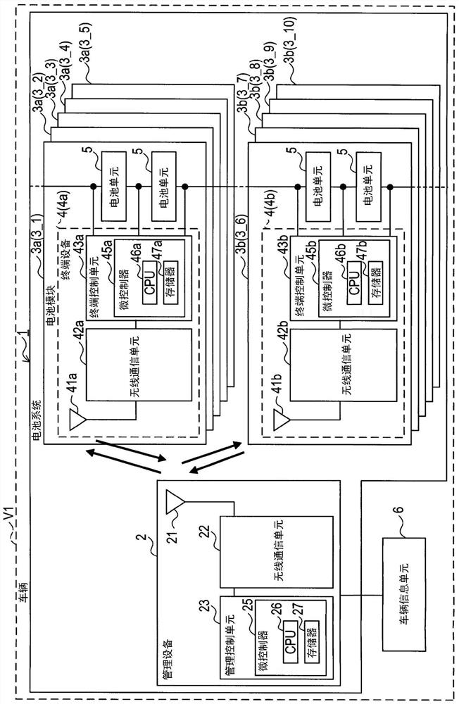
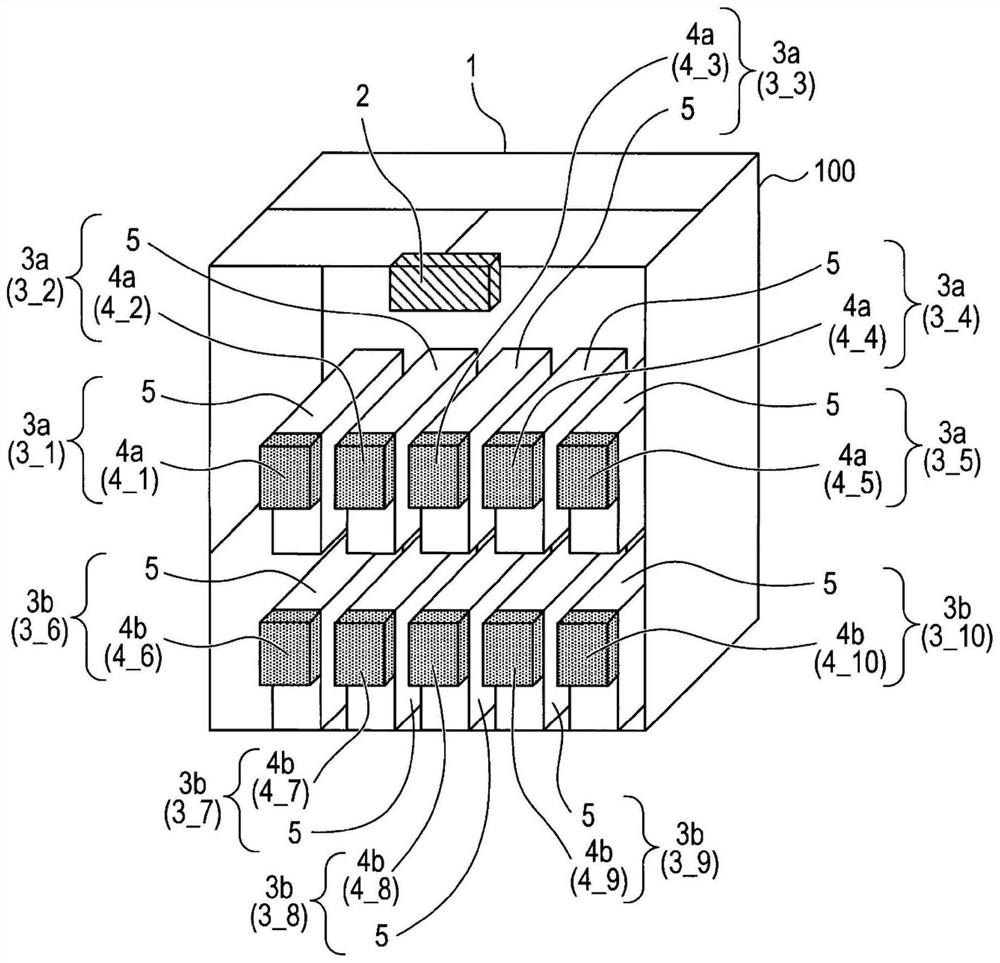
[0027] refer to figure 1 and figure 2 The configuration of the communication system 1 according to the present embodiment is described.
[0028] The communication system 1 is installed on a vehicle V1. The communication system 1 includes a management device 2 and battery module groups 3 . The communication system 1 may include a vehicle information unit 6 . The vehicle information unit 6 includes a plurality of in-vehicle sensors and devices that detect the state of the vehicle V1. More specifically, a wheel speed sensor, an acceleration sensor, a yaw rate sensor, etc. may be included.
[0029] Each of the individual battery modules (3-1 to 3-10) is similarly configured. A battery module 3 - 1 includes a terminal 4 and at least one battery unit 5 . That is, the communication system 1 includes a plurality of terminal devices 4 . The management device 2 performs wireless communication with each terminal device 4 . Each terminal device 4 acqu...
Deformed example 1
[0152] exist Figure 10 , the wireless communication unit 22 of Modification 1 (hereinafter referred to as wireless communication unit 22B) can be configured as shown. exist Figure 10 In the wireless communication unit 22B of Modification 1 shown in Figure 4 The first filter 223 , the second filter 224 , and the switch 225 included in the wireless communication unit 22A shown in , may be replaced by a duplexer 226 .
[0153] The duplexer 226 is a three-terminal filter located at the entrance from the antenna 21 (ie, at the exit to the antenna 21 ) and separates two frequency bands used in the communication system 1 . The duplexer 226 includes terminals 601 to 603 . The terminal 603 is connected to the antenna 21 . Terminal 602 is connected to transceiver switch 401 in first transceiver 221 . Terminal 603 is connected to transceiver switch 401 in second transceiver 222 .
[0154]In Modification 1, when the switching unit 65 switches the wireless communication unit 22B i...
Deformed example 2
[0157] exist Figure 11 , the wireless communication unit 22 (hereinafter referred to as wireless communication unit 22C) in Modification 2 may be configured as shown. Figure 11 The wireless communication unit 22C of Modification 2 shown in the Figure 4 The filter 227 between the switch 225 and the antenna 21 in the wireless communication unit 22A shown in . Filter 227 has two terminals. One of the two terminals of the filter 227 is connected to the antenna 21 , and the other terminal is connected to the switch 225 . In this embodiment, the filter 227 may be a BPF that passes the first frequency band and the second frequency band.
[0158] With this change, one of the three terminals of the switch 225 in the wireless communication unit 22C is connected to the above-described filter 227 instead of the antenna 21 . In Modification 2, when switching the wireless communication unit 22C into the above-described four states, the switching unit 65 outputs a switching signal, as...
PUM
 Abstract
Description
Claims
Application Information
 - R&D
- Intellectual Property
- Life Sciences
- Materials
- Tech Scout
- Unparalleled Data Quality
- Higher Quality Content
- 60% Fewer Hallucinations
Browse by: Latest US Patents, China's latest patents, Technical Efficacy Thesaurus, Application Domain, Technology Topic, Popular Technical Reports.
© 2025 PatSnap. All rights reserved.Legal|Privacy policy|Modern Slavery Act Transparency Statement|Sitemap|About US| Contact US: help@patsnap.com


