

Mud filter-pressing dehydration test device and test method
A technology of filter press dehydration and test equipment, which is applied in separation methods, chemical instruments and methods, water/sludge/sewage treatment, etc., and can solve problems that affect the accuracy of test results, are difficult to disassemble, and are dangerous
Pending Publication Date: 2021-04-23
CHINA RAILWAY 14TH BUREAU GRP LARGE SHIELD ENG CO LTD +1
View PDF6 Cites 1 Cited by
- Summary
- Abstract
- Description
- Claims
- Application Information
AI Technical Summary
Problems solved by technology
However, the existing filter press test device has the following problems: 1. The structure is complex, difficult to disassemble and assemble, and is not suitable for use on the construction site
2. The precision of the pressure adjustment of the filter press test device is not enough, and the accurate value cannot be obtained
3. The existing filter press test device is usually installed with a loading medium after injecting the mud sample,
Method used
View moreImage
Smart ImageViewing Examples

Examples
 PUM
 Abstract
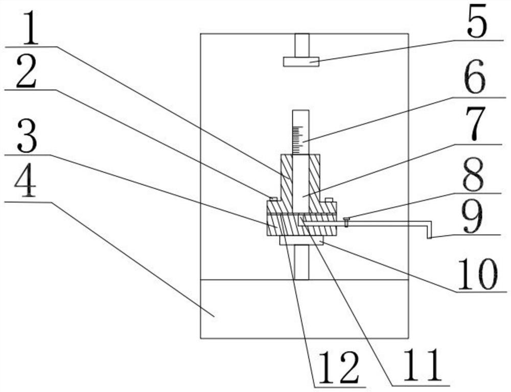
The invention relates to a mud filter pressing dehydration test device and a test method. According to the technical scheme, the mud filter-pressing dehydration test device comprises a pressurizing assembly and a filter-pressing assembly which are independent of each other, the pressurizing assembly comprises a universal testing machine loading device, and the universal testing machine loading device comprises a pressurizing shaft and a base; the filter-pressing assembly comprises a slurry containing column, a through cylindrical cavity is formed in the slurry containing column, a movable bearing capable of moving in the axial direction is arranged in the cylindrical cavity, the bottom of the slurry containing column is connected with a filter-pressing base, and geotechnical cloth is arranged between the slurry containing column and the filter-pressing base; and the filter-pressing base is placed on the base and is provided with a drainage structure. The pressurizing assembly and the filter-pressing assembly are independent of each other, a slurry sample can be independently injected into the filter-pressing assembly, and reverse loading can be carried out, so that the phenomenon that air exists between the slurry sample and a loading medium is avoided. A universal testing machine can accurately control the pressurizing pressure value and the pressurizing speed, and the phenomenon of mud splitting when the air pressure is too high is avoided.
Description
technical field [0001] The invention relates to the technical field of filter press test devices, in particular to a mud filter press dehydration test device and a test method. Background technique [0002] In conventional geotechnical engineering such as bored piles, underground diaphragm walls, pipe jacking, mud-water shields, etc., mud is widely used for its excellent wall protection, slag-carrying functions, low cost, and easy acquisition. However, a large amount of waste mud will inevitably be produced during the construction process. The waste mud has high moisture content and high fine particle content, which is difficult to dispose or handle. Improper treatment will easily cause secondary pollution, so it must be dehydrated and reduced. At present, it is widely used to use a flocculant to dehydrate it first, and then use a mechanical dehydration method to treat it. The essence of mechanical dehydration is to force the pore water out of the drainage channel in the mu...
Claims
Login to View More Application Information
Patent Timeline
 IPC IPC(8): B01D25/12C02F11/122
CPCB01D25/12B01D25/003C02F11/122
Inventor霍翼聂满录刘四进张振国娄瑞王军王建华
OwnerCHINA RAILWAY 14TH BUREAU GRP LARGE SHIELD ENG CO LTD