

Wire lifting device of wire drawing machine
Patent Information
- Authority / Receiving Office
- CN · China
- Current Assignee / Owner
- 江西丰莱科技有限公司
- Publication Date
- 2021-04-23
Smart Images
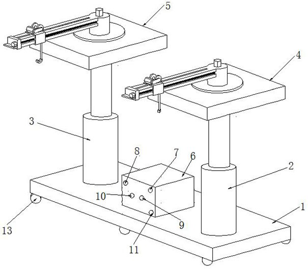
Figure 1 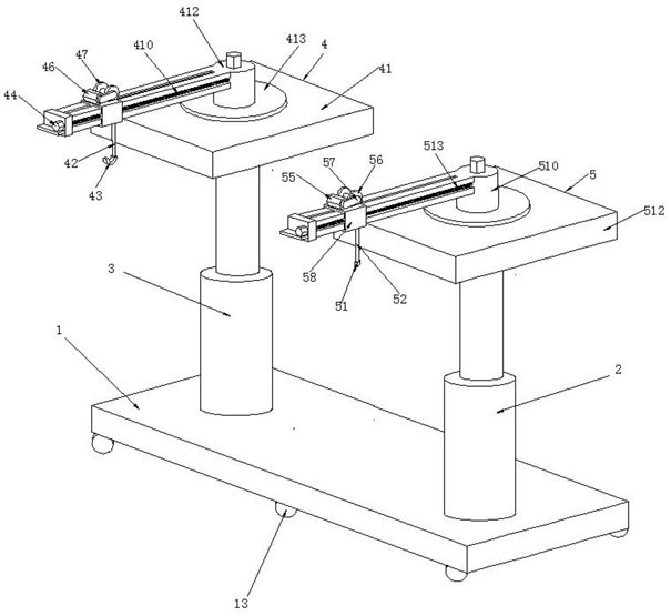
Figure 2 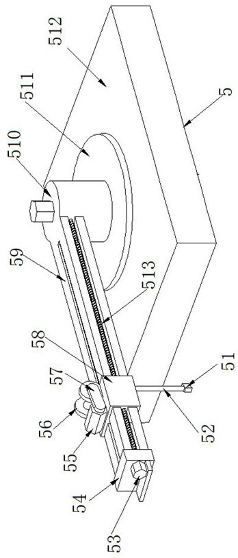
Figure 3
Abstract
Description
technical field
[0001] The invention relates to the technical field of wire drawing machines, in particular to a wire lifting device for a wire drawing machine. Background technique
[0002] Wire drawing machine is also called wire drawing machine. It is a widely used mechanical equipment in industrial applications. It is widely used in machinery manufacturing, metal processing, petrochemical, plastic, bamboo and wood products, wire and cable and other industries. Wire drawing machine is used in wire and cable In the industry, it is necessary to lift wires and cables, so wire drawing machine wire lifting devices are needed.
[0003] However, the current wire lifting device of the wire drawing machine still cannot lift the wires at different positions, and the versatility is poor. The problem of slow speed.
[0004] Therefore, it is necessary to design a method that can lift the wires at different positions and has strong versatility. The auxiliary mechanism is used to assi...