Aluminum bar equidistant cutting equipment

A technology of isometric cutting, equipment, applied in the direction of metal sawing equipment, metal processing equipment, manufacturing tools

Active Publication Date: 2021-04-23
肇庆市尚乔铝业有限公司
View PDF12 Cites 1 Cited by
  • Summary
  • Abstract
  • Description
  • Claims
  • Application Information

AI Technical Summary

Problems solved by technology

[0005] In order to overcome the disadvantages of manually moving the aluminum rod and stepping on the pedal for cutting in order to overcome the cutting work of the above-mentioned patent, the technica...

Method used


Image

  • Aluminum bar equidistant cutting equipment
  • Aluminum bar equidistant cutting equipment
  • Aluminum bar equidistant cutting equipment

Examples


Embodiment 1

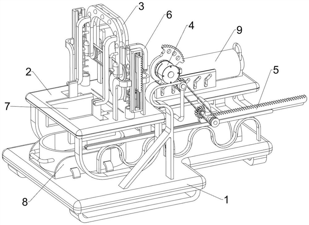
[0030] An equipment for isometric cutting of aluminum rods such as Figure 1 to Figure 3 As shown, it includes a base 1, a workbench 2, a cutting mechanism 3 and a drive mechanism 4. The top of the base 1 is connected to the workbench 2. There is an opening on the left side of the top of the workbench 2. The top of the workbench 2 is equipped with a cutting mechanism 3. The base 1. A driving mechanism 4 is installed on the top, and the driving mechanism 4 is connected with the cutting mechanism 3 in transmission.

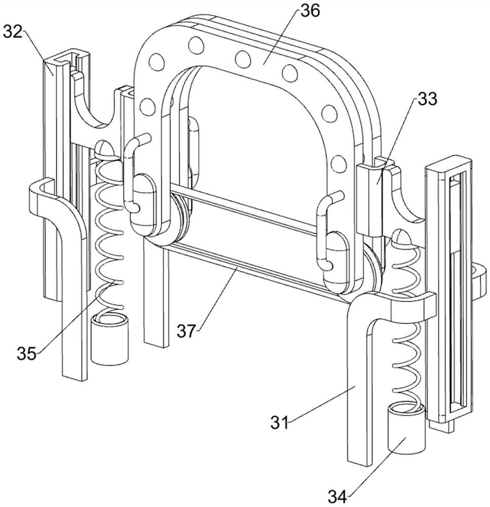
[0031] Cutting mechanism 3 comprises the first fixed mount 31, the first guide rail frame 32, connecting frame 33, sleeve seat 34, support spring 35, mounting frame 36 and electric cutting belt 37, the front and rear sides of workbench 2 top left sides all There are two first fixed mounts 31 symmetrically connected on the left and right sides, a first guide rail frame 32 is connected between the two first fixed mounts 31 on the left and right sides, and a connecting...

Embodiment 2

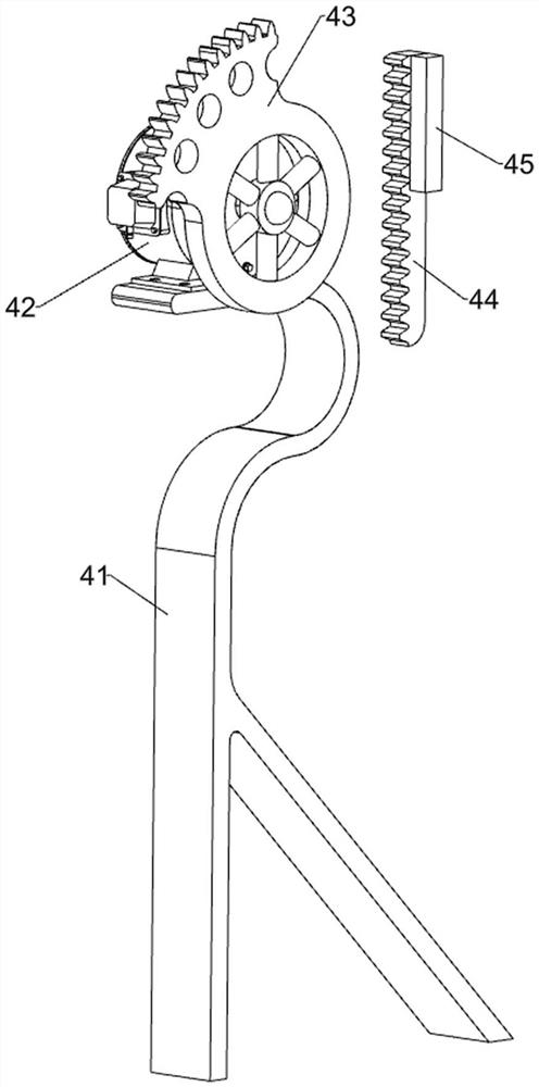
[0035] On the basis of Example 1, such as figure 1 and Figure 4As shown, a push mechanism 5 is also included, and the push mechanism 5 includes a first positioning frame 51, a first gear 52, a transmission belt set 53, a second positioning frame 54, a one-way clutch 55, a second gear 56, a second tooth Bar frame 57, the second guide rail frame 58, push block 59 and handle 510, the workbench 2 front side is connected with the first positioning frame 51, is connected with the first gear 52 in rotation on the first positioning frame 51, and the first gear 52 and Sector gear 43 cooperates, and the workbench 2 front sides are connected with the second spacer 54, and the second spacer 54 is positioned at the right side of the first spacer 51, and the rotation type in the second spacer 54 is connected with the rotating rod, and the rotating rod is connected with the first positioning frame 51. A drive belt set 53 is connected between the transmission shafts of a gear 52, a one-way ...

Embodiment 3

[0038] On the basis of Example 2, such as figure 1 and Figure 5 As shown, a clamping mechanism 6 is also included. The clamping mechanism 6 includes a mounting base 61, a directional splint frame 62, a return spring 63, a wedge bar 64, a wedge frame 65 and a limit side plate 66. The top of the workbench 2 Two mounts 61 are connected symmetrically on the left side front and back, the mounts 61 are positioned at the inner side of the first fixed mount 31, the mounts 61 are slidably connected with a directional splint frame 62, and the directional splint frame 62 and the mount 61 are connected with Back-moving spring 63, directional splint frame 62 right sides are connected with wedge-shaped block bar 64, and mounting frame 36 right sides are connected with two wedge-shaped block frames 65 symmetrically before and after, wedge-shaped block frame 65 cooperates with wedge-shaped block bar 64, workbench 2 Two limiting side plates 66 are symmetrically connected to the top front and...


PUM


Abstract

The invention relates to cutting equipment, in particular to aluminum bar equidistant cutting equipment. According to the aluminum bar equidistant cutting equipment, aluminum bars can be automatically cut, and the aluminum bars can be automatically moved. The aluminum bar equidistant cutting equipment comprises a base and a driving mechanism; a workbench is connected to the base, an opening is formed in one side of the workbench, and a cutting mechanism is installed on the workbench; and the driving mechanism is installed on the base, and the driving mechanism is in transmission connection with the cutting mechanism. According to the aluminum bar equidistant cutting equipment, the cutting mechanism can be driven to work through the driving mechanism, the aluminum bars can be cut into aluminum sheets through the cutting mechanism, the aluminum bars can be intermittently pushed to move through a pushing mechanism, and therefore the effects of automatically cutting the aluminum bars and automatically moving the aluminum bars are achieved.

Description

technical field [0001] The invention relates to a cutting device, in particular to an equidistant cutting device for aluminum rods. Background technique [0002] When processing special products, aluminum sheets are needed. Aluminum sheets are cut from aluminum rods. At present, manual cutting and machine cutting are usually used to cut aluminum rods. After retrieval, the publication number is: patent of CN206997915U , discloses a kind of alloy aluminum rod cutting equipment for long strips, including a support plate, a telescopic rod, a top plate, a push rod, and a motor; the operating table is welded and fixed on the top of the support rod; On the operating table; the support rod is welded and fixed around the bottom plate; the saw blade is connected to the motor for rotation; the return spring is connected between the bottom plate and the support plate; the support plate is welded and fixed on the top of the telescopic rod The telescopic rod is welded to the top of the b...

Claims


Application Information

Patent Timeline
IPC IPC(8): B23D53/00B23D55/02B23D55/04B23D55/08
CPCB23D53/003B23D55/02B23D55/04B23D55/088
Inventor 彭峰
Owner 肇庆市尚乔铝业有限公司
Why Eureka
Try Eureka