Eureka AIR delivers breakthrough ideas for toughest innovation challenges, trusted by R&D personnel around the world.

Mounting device for back-to-back double zipper pullers

An installation device and double zipper technology, which is applied in the field of garment processing, can solve problems such as low production efficiency, long assembly process, and manual installation cannot be completed, so as to reduce production costs, improve economic benefits, and improve work efficiency and production capacity. Effect

Active Publication Date: 2021-04-27
安徽星星服装股份有限公司
View PDF5 Cites 0 Cited by
  • Summary
  • Abstract
  • Description
  • Claims
  • Application Information

AI Technical Summary

Problems solved by technology

The existing zipper puller assembly device can only assemble one zipper puller into the zipper at a time, and when using the double slider closed-end zipper to thread the zipper, it is necessary to wear one of the zipper pullers first, then change the direction of the zipper and then wear the other. One zipper puller, the whole assembly process takes a long time and the production efficiency is low
[0006] Among them, such as figure 1 As shown, in the process of assembling the double-head zipper, it is relatively easy to insert the chain elements into the large end of the slider, but it is very difficult to insert the chain elements into the tail of the slider, which cannot be completed by manual installation, so it is necessary to design a double-zipper installation device , to reduce installation difficulty and improve production efficiency

Method used


Image

  • Mounting device for back-to-back double zipper pullers
  • Mounting device for back-to-back double zipper pullers
  • Mounting device for back-to-back double zipper pullers

Examples


Embodiment Construction

[0024] It should be noted that, in the case of no conflict, the embodiments in the present application and the features in the embodiments can be combined with each other. The present invention will be described in detail below with reference to the accompanying drawings and examples.

[0025] Figure 2 ~ Figure 4 Some embodiments according to the invention are shown.

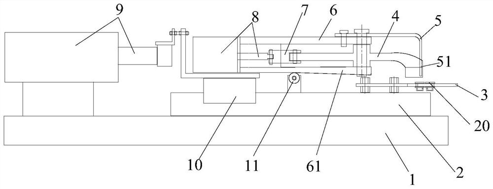
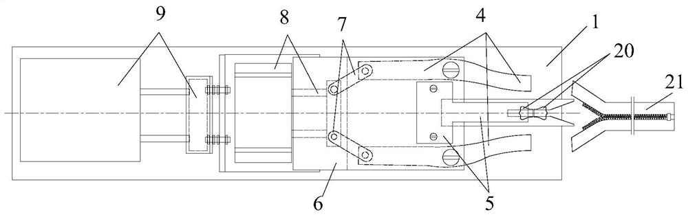
[0026] Such as Figure 2~4 As shown, a back-to-back installation device for double zipper pulls includes: a base 1, a sliding guide rail 2, a slider 10, a mounting bracket 6 installed on the slider 10, a linear cylinder-8, and a rear end of the linear cylinder-8. Linear cylinder two 9, movable clamp 4 and L-shaped baffle plate 5 that the front end of mounting bracket 6 is provided with, and the installation guide plate 3 that movable clamp 4 undersides are provided with.

[0027] Specifically, such as figure 2 As shown, the base 1 is fixed on the workbench as the base of the whole device, and the sliding g...


PUM


Abstract

The invention discloses an installation device for back-to-back double zipper pullers, and the device comprises a sliding guide rail which is provided with a sliding block; a mounting guide plate, wherein a puller placing guide groove is formed in the front part of the mounting guide plate; a mounting bracket, wherein a linear cylinder II and an L-shaped baffle plate are arranged at the rear end of the mounting bracket, the L-shaped baffle plate is arranged at the front end of the mounting bracket, and the front part of the L-shaped baffle plate extends to the upper side of the puller placing guide groove; movable clamps located on the two sides of the L-shaped baffle and rotationally connected with the mounting bracket, and first linear air cylinders are arranged at the rear ends of the movable clamps; wherein the first linear air cylinder drives the movable clamp to rotate and is used for clamping a cloth belt located between the L-shaped baffle plate and the front end of the movable clamp, and the second linear air cylinder drives the mounting bracket to move and then drives the cloth belt to move backwards, so that zipper teeth on the cloth belt penetrate into the two pull heads, and assembling of a zipper with the double zipper pullersis completed. According to the device, the difficulty that the zipper teeth penetrate through the tail of the puller is reduced, and meanwhile, by adopting a semi-automatic assembling mode, the working efficiency and the productivity of the whole process are improved.

Description

technical field [0001] The invention relates to the technical field of garment processing, in particular to a back-to-back double zipper slider installation device. Background technique [0002] Zipper is a connecting piece that relies on the continuous arrangement of chain teeth to make items merge or separate. It is widely used in daily necessities such as clothing, bags, and tents. [0003] Existing zippers include multiple types, such as single-opening zippers and double-opening zippers. As the most common and commonly used zipper, the single-head closed-end zipper is widely used in quilts, clothing pockets, trousers and other places; among them, the single-opening zipper refers to the zipper that is injection molded with a top stop and a bottom stop. There is generally a slider on the top. When the single-opening zipper is pulled, the slider moves from the end where the bottom end is located to the end where the end is located. It can realize the closing of two paralle...

Claims


Application Information

Patent Timeline
IPC IPC(8): A44B19/62
CPCA44B19/62
Inventor 程若维吴汉萍
Owner 安徽星星服装股份有限公司
Why Eureka
Eureka Blog
Learn More