Distillation reaction kettle with protective structure for chemical production
A protective structure and chemical production technology, which is applied in the field of distillation reactors, can solve the problems that the release force cannot be adjusted according to the demand, the stirring shaft is damaged, and the gas outlet valve cannot be adjusted according to the demand.
- Summary
- Abstract
- Description
- Claims
- Application Information
AI Technical Summary
Problems solved by technology
Method used
Image

Examples
Embodiment 1
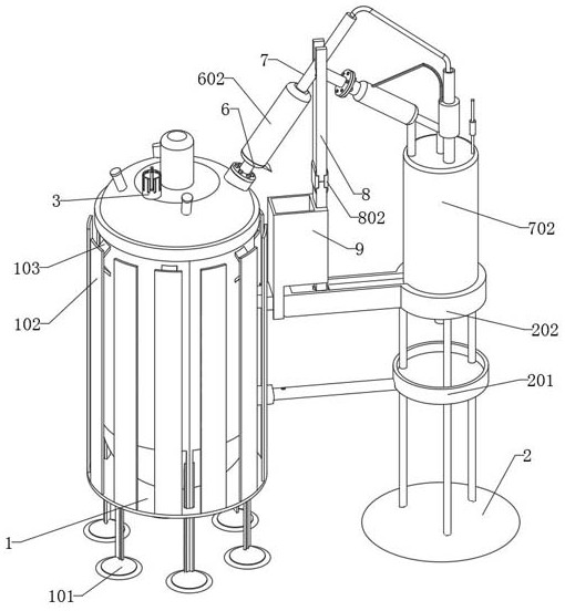
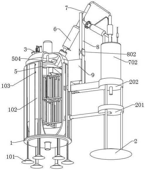
[0035] as attached Figure 1 to Figure 10 As shown, the distillation reaction kettle with protective structure for chemical production in the preferred embodiment of the present invention includes a main body 1, a side piece 2, a mounting head 3, a moving piece 4, a buffer piece 5, a connecting pipe 6, an overturning pipe 7, and a support plate 8 and collection bin 9. The main body 1 is the body of the distillation reactor, and the bottom of the main body 1 is a plate-like structure with a middle protrusion; the side piece 2 is at the bottom of the side of the main body 1, and the inner end of the receiving piece 201 of the side piece 2 is in contact with the side of the main body 1 connected, and the top of the mounting part 202 of the side piece 2 is connected with the top of the side of the main body 1 . The bottom of the installation head 3 is installed in the top threaded hole of the main body 1 through threads. The bottom end of the connecting pipe 6 is connected to th...
Embodiment 2
[0042] In a preferred embodiment, the moving part 4 also includes a clamping plate 404, the clamping plate 404 is an L-shaped plate structure, and the bottom end of the clamping plate 404 is a wedge-shaped structure, and the top end of the clamping plate 404 is in contact with the outer surface of the pole 403. The end and the bottom are connected, and the clamping plate 404 plays a role of being inserted into the clamping groove 303 at different positions, so that the pressing plate 402 can be fixed at an appropriate height for use, thereby adjusting the degree of pressure relief.
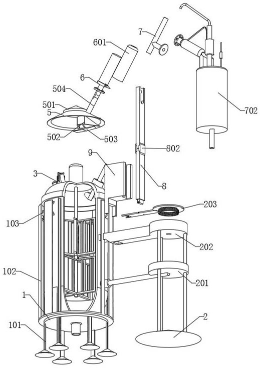
[0043] Further, the buffer member 5 also includes a delivery tube 504, the delivery tube 504 is a cylindrical tubular structure, and the delivery tube 504 is connected to the side of the buffer member 5, and the inner end of the delivery tube 504 is a trumpet-shaped structure; the delivery tube The outside of the outer end of 504 is fixedly connected with the top of the main body 1, and the conveyi...
Embodiment 3
[0045] In a preferred embodiment, the connecting tube 6 includes a cannula 601 and a sleeve 602 , the connecting tube 6 is a cylindrical tubular structure with a protrusion in the middle, and the top end of the connecting tube 6 is provided with the cannula 601 . The cannula 601 is a cylindrical tubular structure, and the outer end of the cannula 601 is a horn-shaped structure, and the bottom of the inner end of the cannula 601 is provided with three circular holes. A sleeve 602 is sleeved on the outside of the cannula 601 , and the top of the inner end of the sleeve 602 is a trumpet-shaped structure. The connecting pipe 6 plays the role of connecting the conveying pipe 504 with the turning pipe 7, so that when the device is in use, after the collection tank 702 has a lot of liquid inside, or after the inside liquid is full, the turning plate 203 can be pressed to turn over, and then Push the support plate 8 upwards, so that the flip tube 7 can move upwards, and then the casin...
PUM
 Abstract
Description
Claims
Application Information
 - R&D
- Intellectual Property
- Life Sciences
- Materials
- Tech Scout
- Unparalleled Data Quality
- Higher Quality Content
- 60% Fewer Hallucinations
Browse by: Latest US Patents, China's latest patents, Technical Efficacy Thesaurus, Application Domain, Technology Topic, Popular Technical Reports.
© 2025 PatSnap. All rights reserved.Legal|Privacy policy|Modern Slavery Act Transparency Statement|Sitemap|About US| Contact US: help@patsnap.com